Nomicon
Used to form nouns, referring to a book of knowledge on the specified topic.
Overview
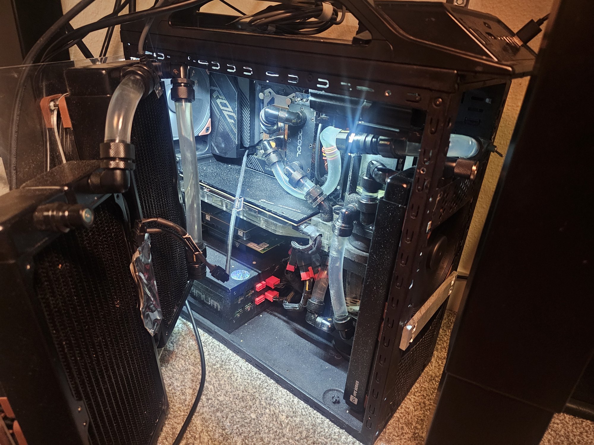
I'm keeping my build logs for this project in reverse-chronological order. This section is for detailing the current system state. Details on my component choices etc. can be found under the [link] Components page.
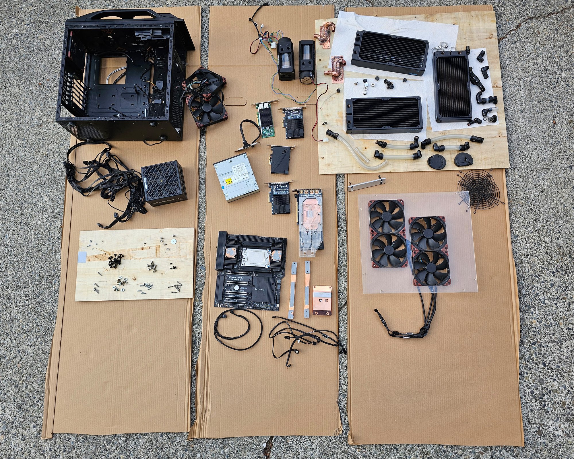
Nomicon Field Kit
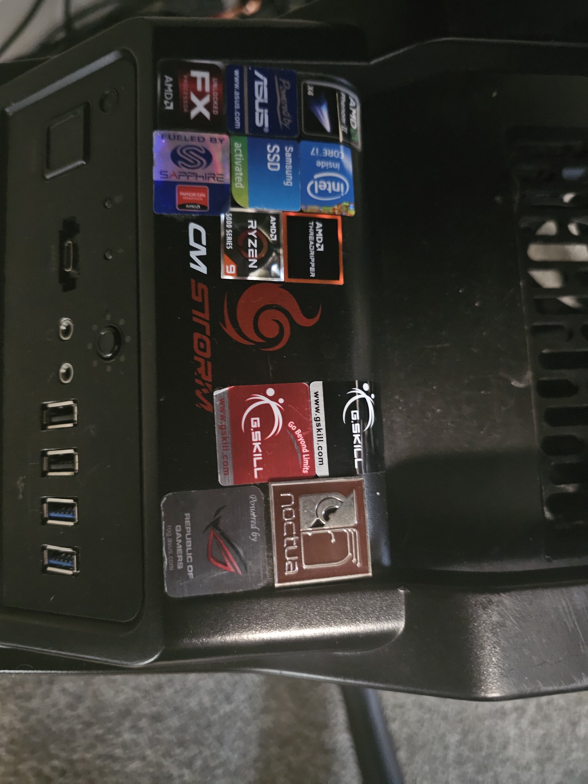
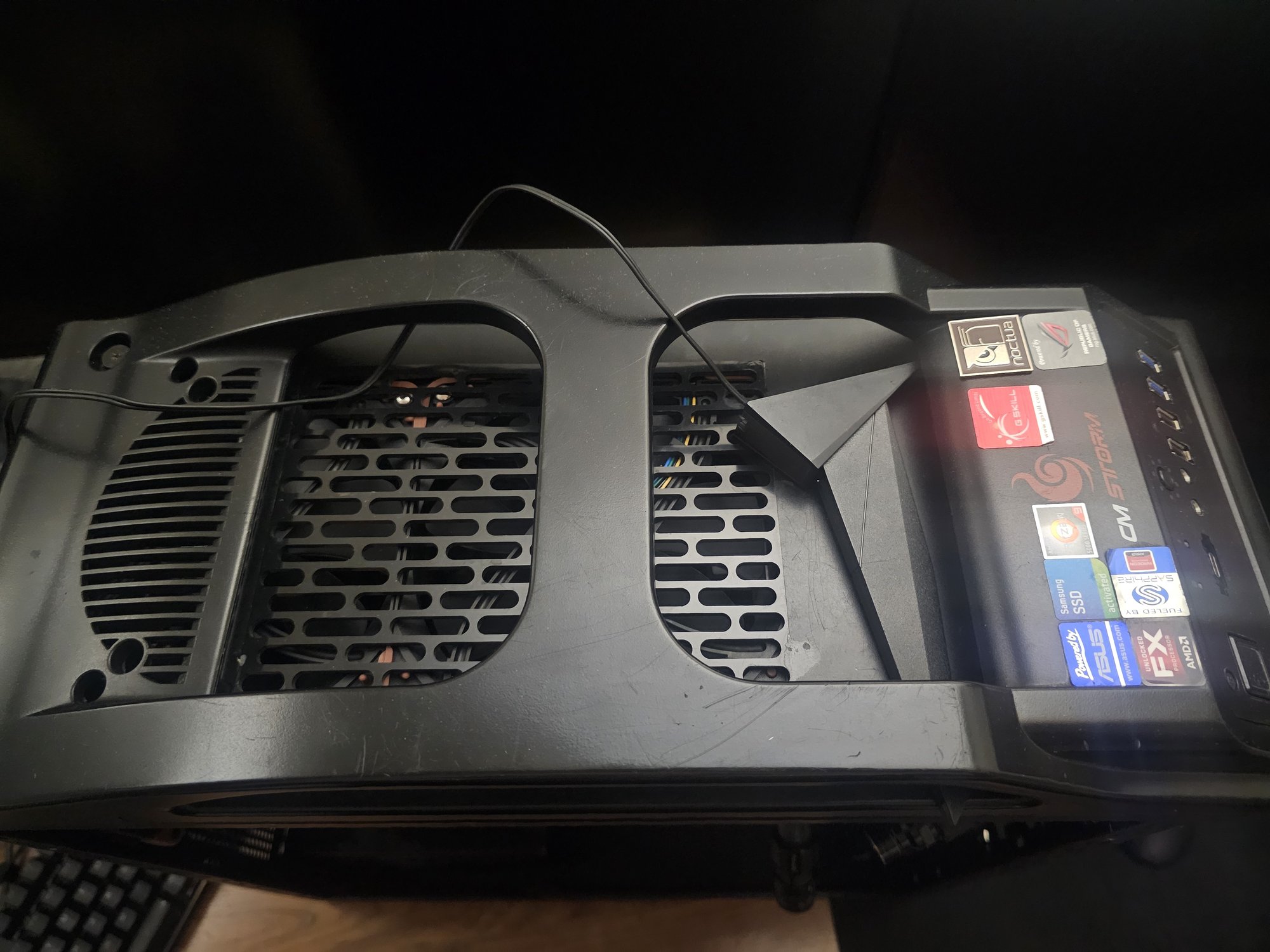
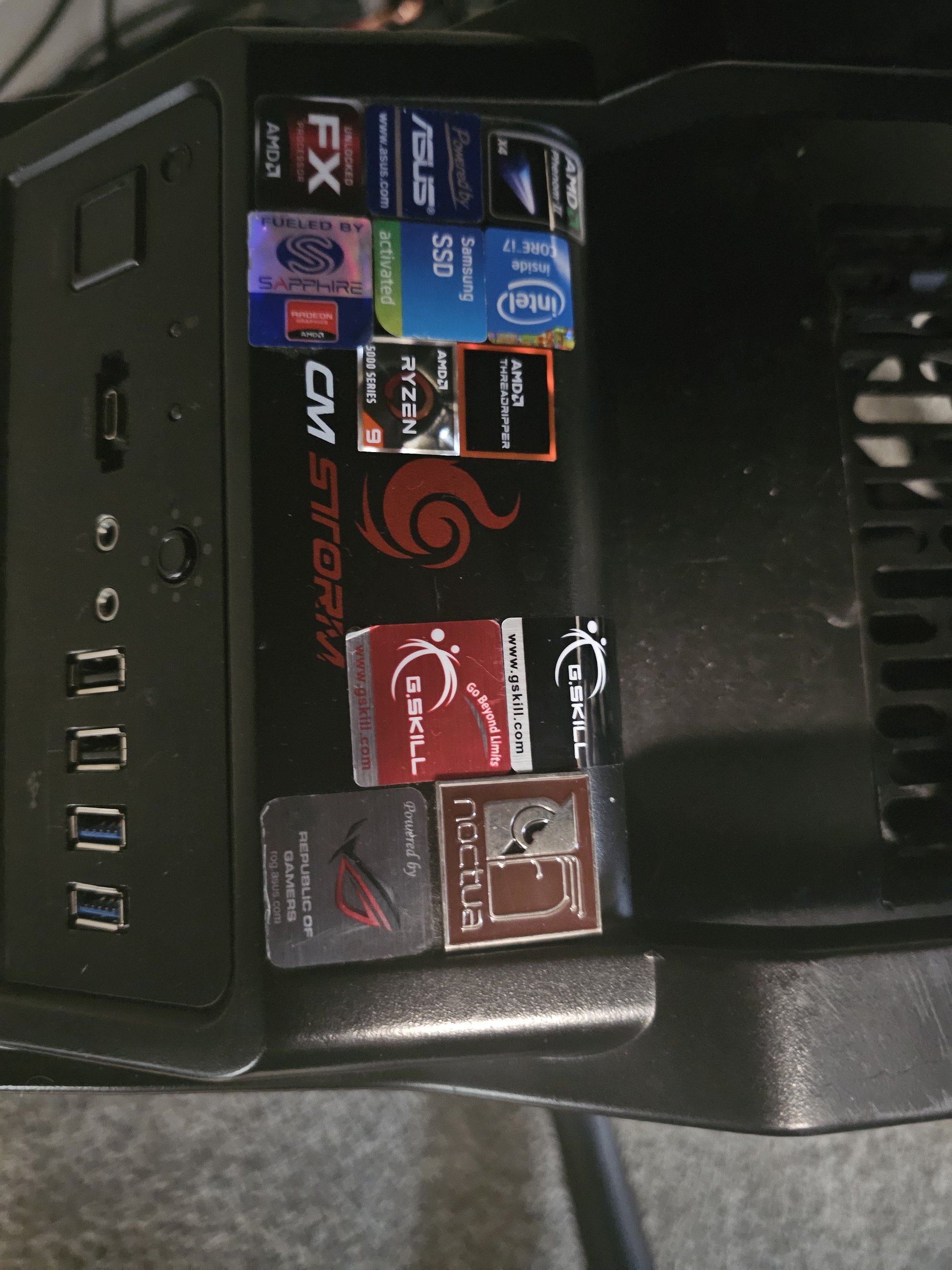
I put every sticker I've ever gotten on the top of the case. I'm really running out of room.
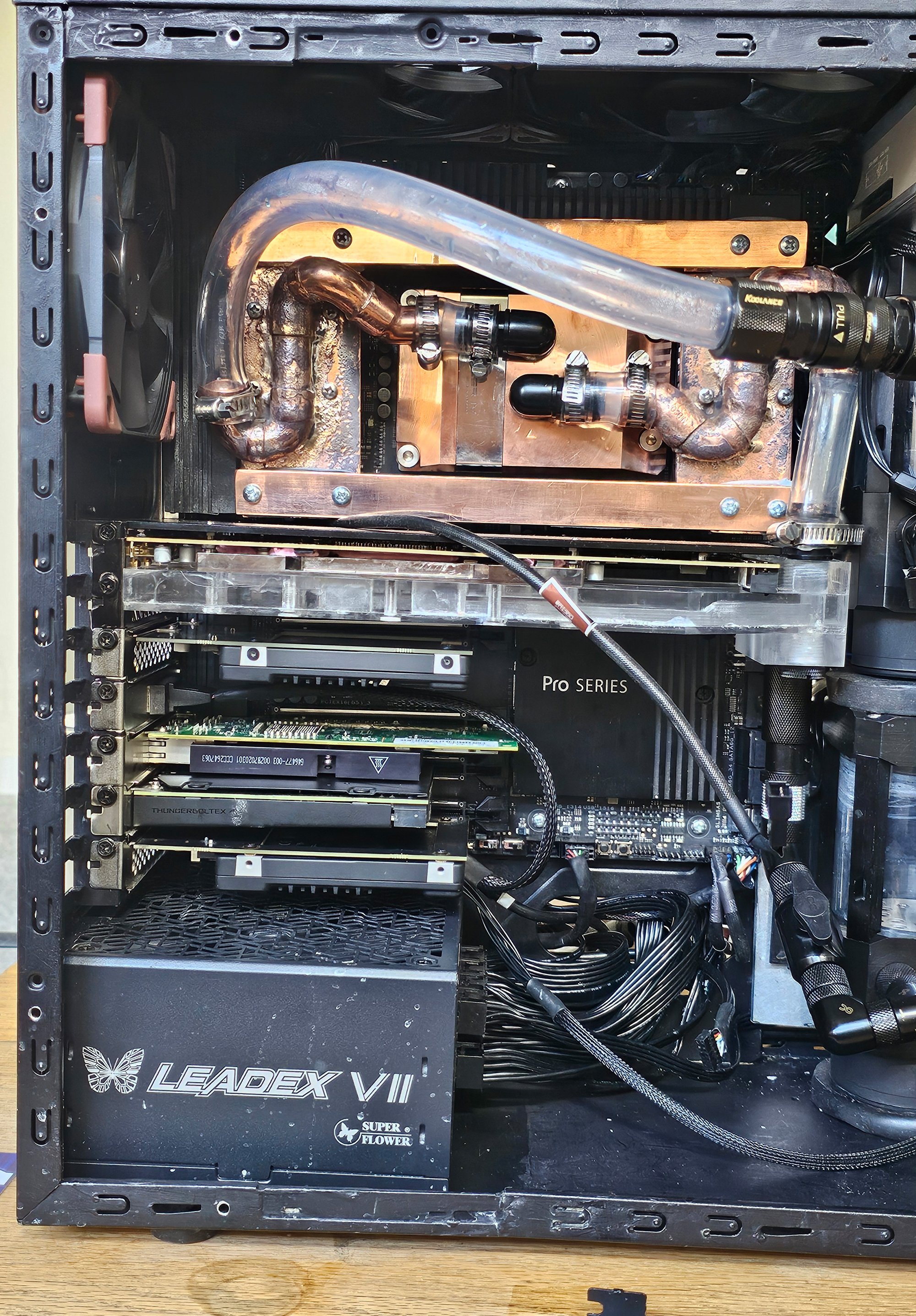
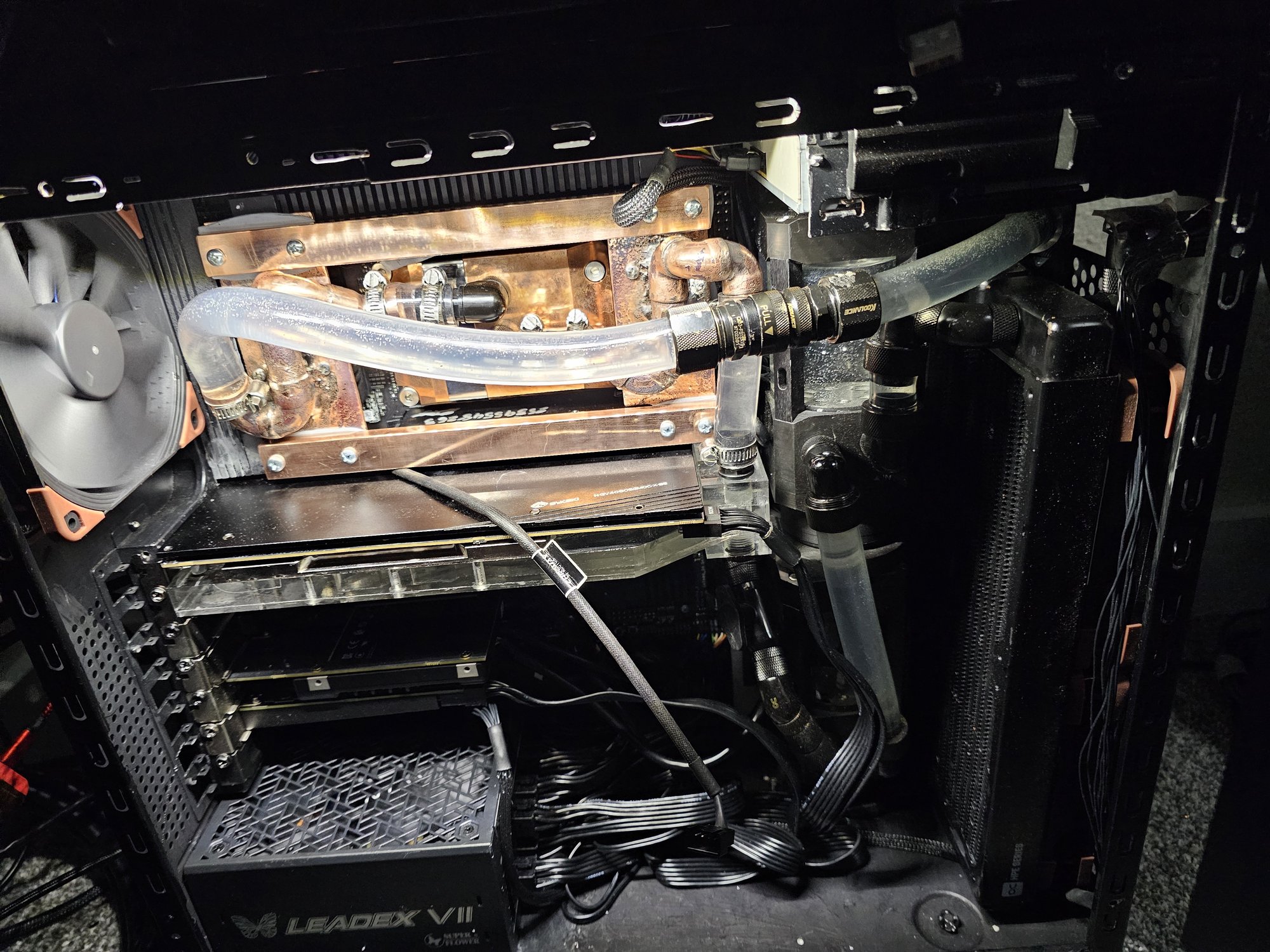
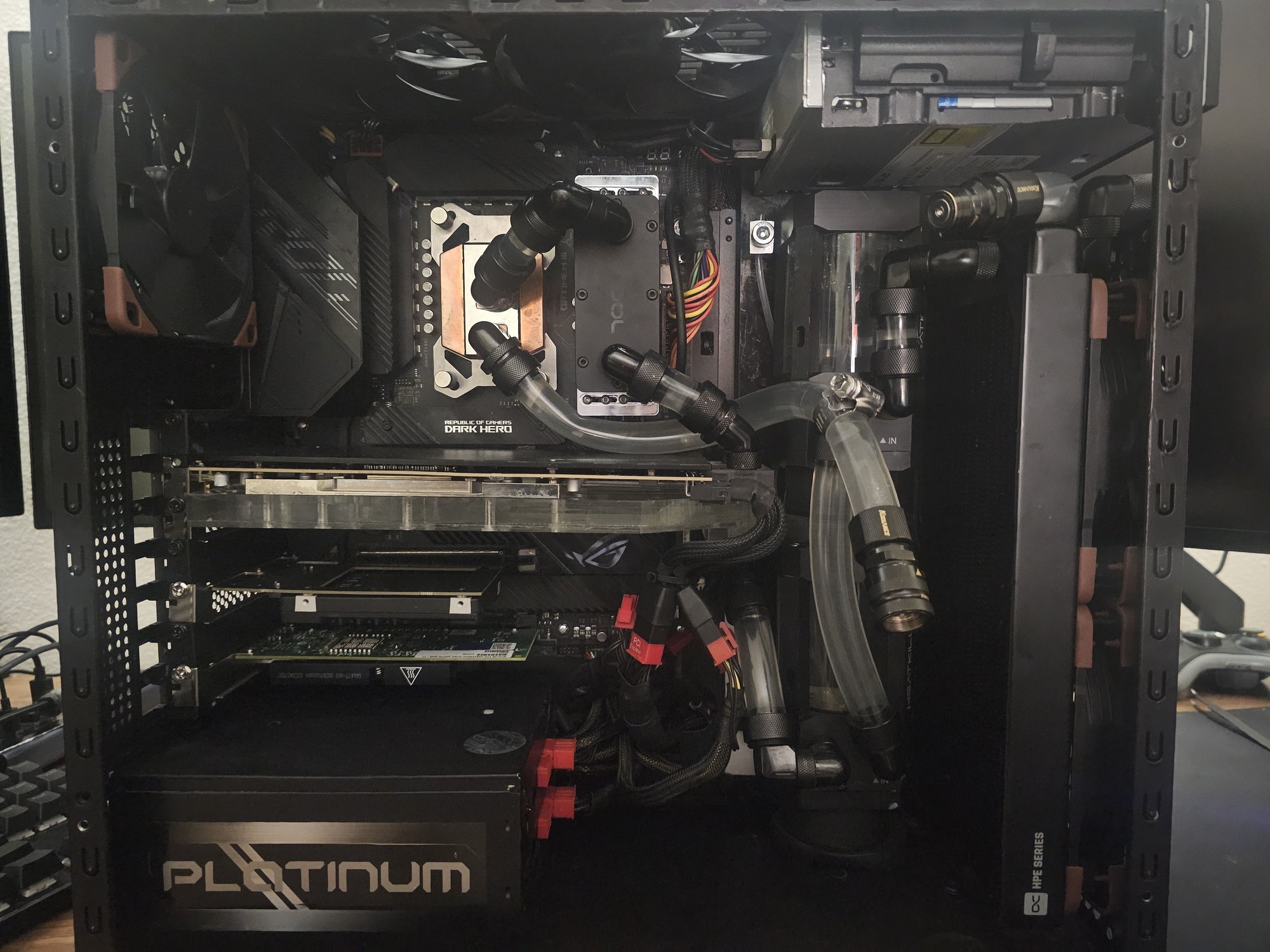
I finally filled all my case's pcie slots! I never thought I'd achieve this.
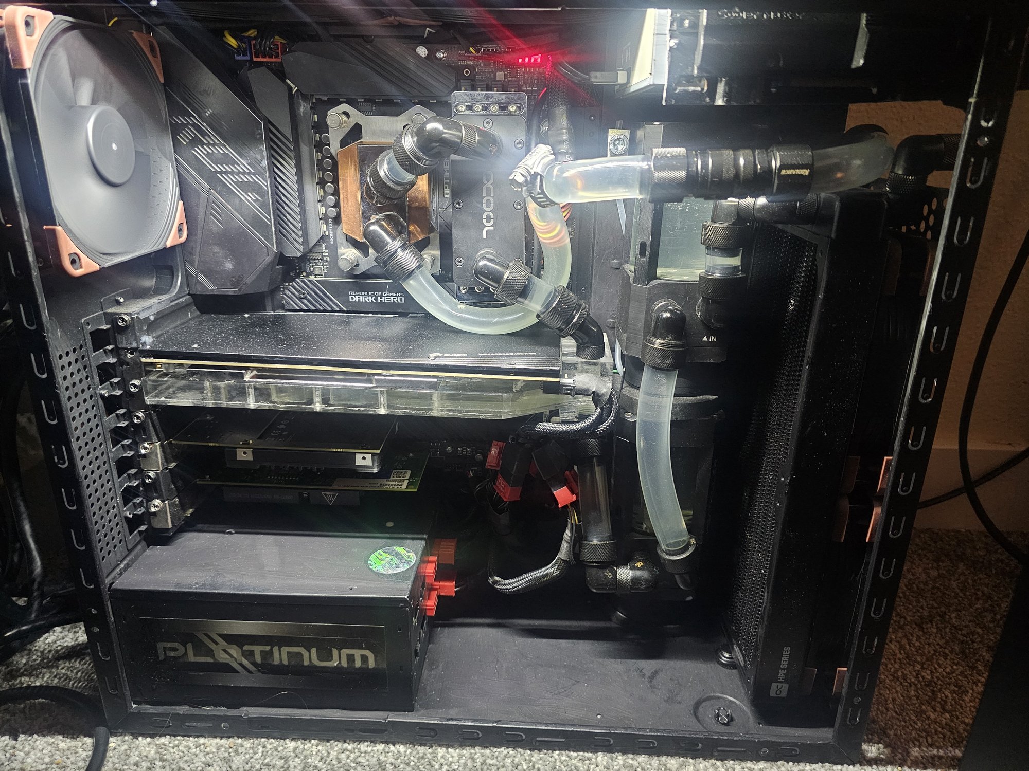
I had to take everything apart to fix a catastrophe, and realized I had a chance to take this photo. It isn't perfect, but it wasn't my main objective at the time.
Specs:
- Threadripper 9960x (Factory PBO, 5.625Ghz)
- 4x32GB GSkill DDR5 6000CL30 ECC
- ASUS TRX50 Sage (rev 1.0)
- Windforce RTX 4080 Super (rev 2.0) @ 3.1Ghz Core, 12.2Ghz Mem
- 2x Optane Gen2 P5800x (800GB + 400GB)
- 3x Various NVMe NAND drives
- Intel x540-T2 10g
- ASUS ThunderboltEX 4 (forced drivers)
- Superflower Leadex VII 1200w 80+ Platinum
- ASUS disk drive
Cooling:
- 2x D5 + Heatkiller Tube (ground + cut to 75mm each)
- sorbothane shock mounted
- 3x 280mm Alphacool HPE (2x 45mm 1x 30mm)
- 8x 140mm Noctua NF-A14 iPPC
- 1x 120mm Noctua NF-A12 iPPC
- Heatkiller Pro IV for Threadripper
- Bykski 4080 Super Windforce block
- Custom CNC rear-port acrylic top
- Handmade VRM + RAM "waterblocks"
- 0% silver phos-copper brazed
- Koolance QD3 quick disconnects
- I want black flakey QD4's so bad
I ❤︎ Acid
I like doing acid flushes to clean my loop. I took it up a notch a few months ago and hand flushed the copper pipes with ~25% sulfuric to try and remove the last of the scale in them, then ran a dilution through my loop along with my usual acetic acid dilution (~30%). I let excesses of each mix together (possibly producing protonated acetic acid) in my spare fill bottle I use for this stuff. All went fine, but I evidently mixed up my fill bottles at some point, and had been topping my loop off with quite strong acid. My nose tipped me off to this when I was performing a top-up, and then I forgot to get around to fixing it.
The siren that eventually went off was when I started experiencing GPU instability. I chalked this up to screwing up thermal pads and having an unreported hot-spot temperature, and I wanted to mess around with my new bucket of UTP-8 putty. I took the side panel off the case and found an extremely slow drip of turqoise and green just beginning to drip onto my 4080 Super's PCB. There was a stalagtite of copper oxides and sulfates coming from a pinhole leak in a joint on one of my copper pipes where the acidic mixture had evidently eaten the solder.
Here is what happens when you run strong acid in your loop for 3+ months:
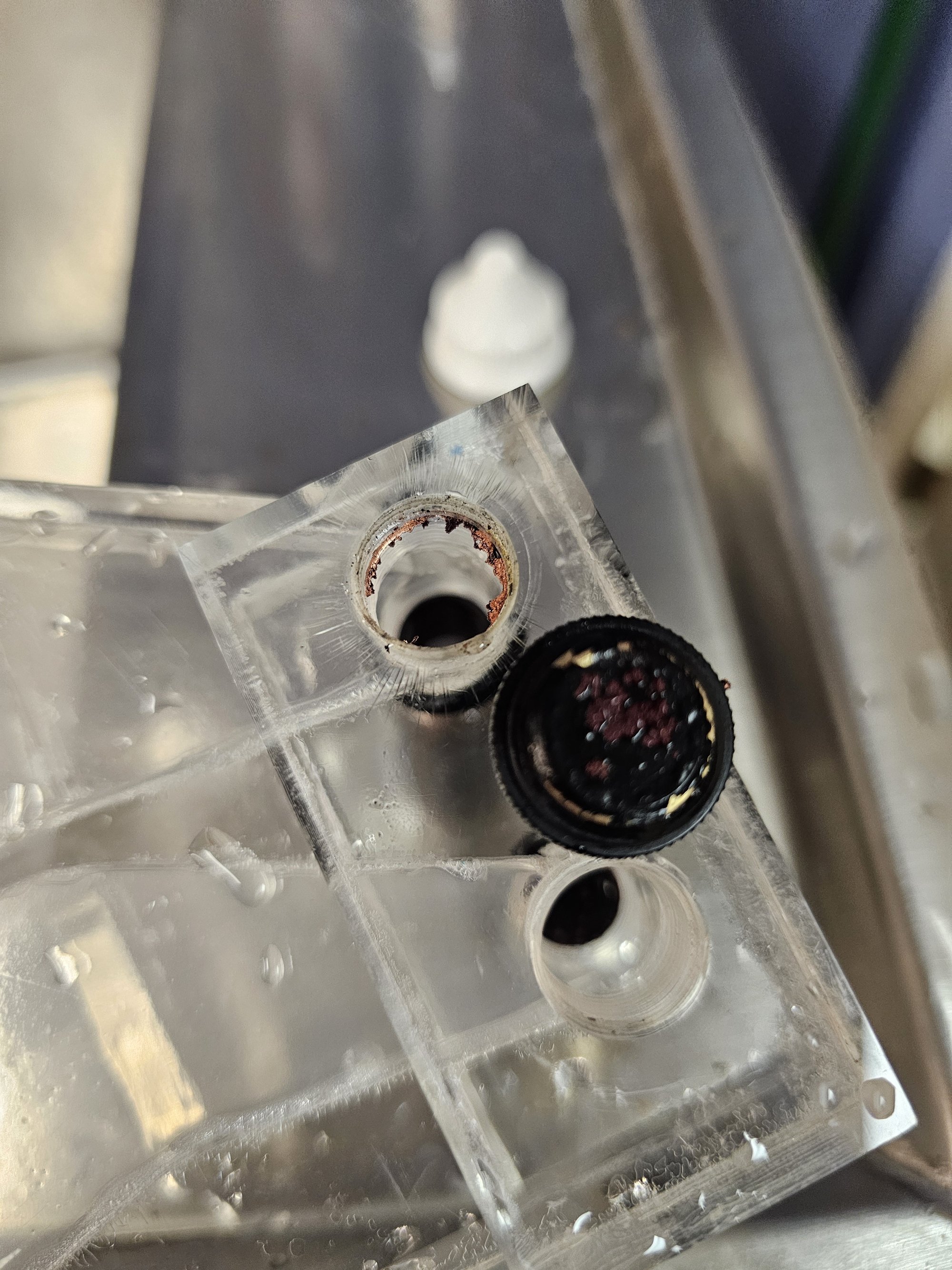
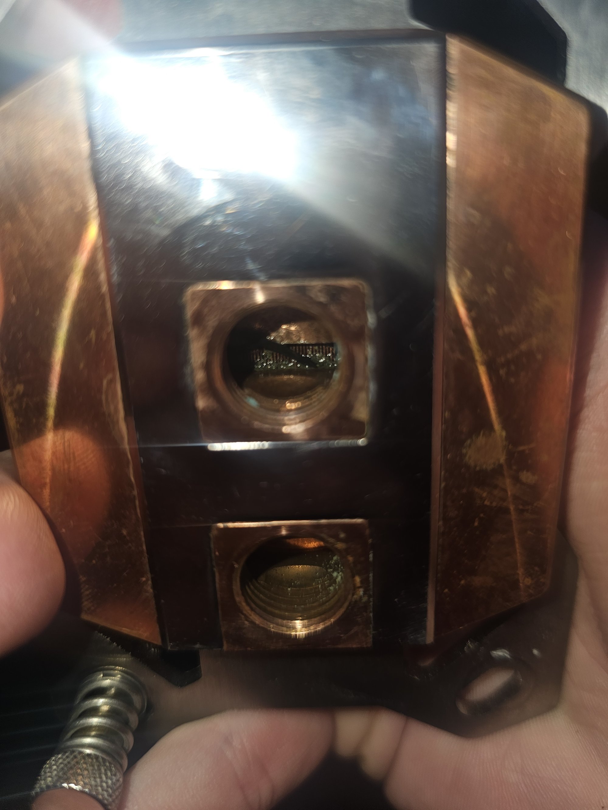
The reservoir top blew me away. I was very very impressed with my loop for running that long like that, and then I thought about basic chemistry. The rest of the loop was in an anerobic environment, so thats likely why it got spared.
3 out of 4 of my Koolance QD3 connectors did not survive. I did not know Koolance was a 40 minute drive away and that they offer pickup, so I ended up waiting 5 days for replacements.
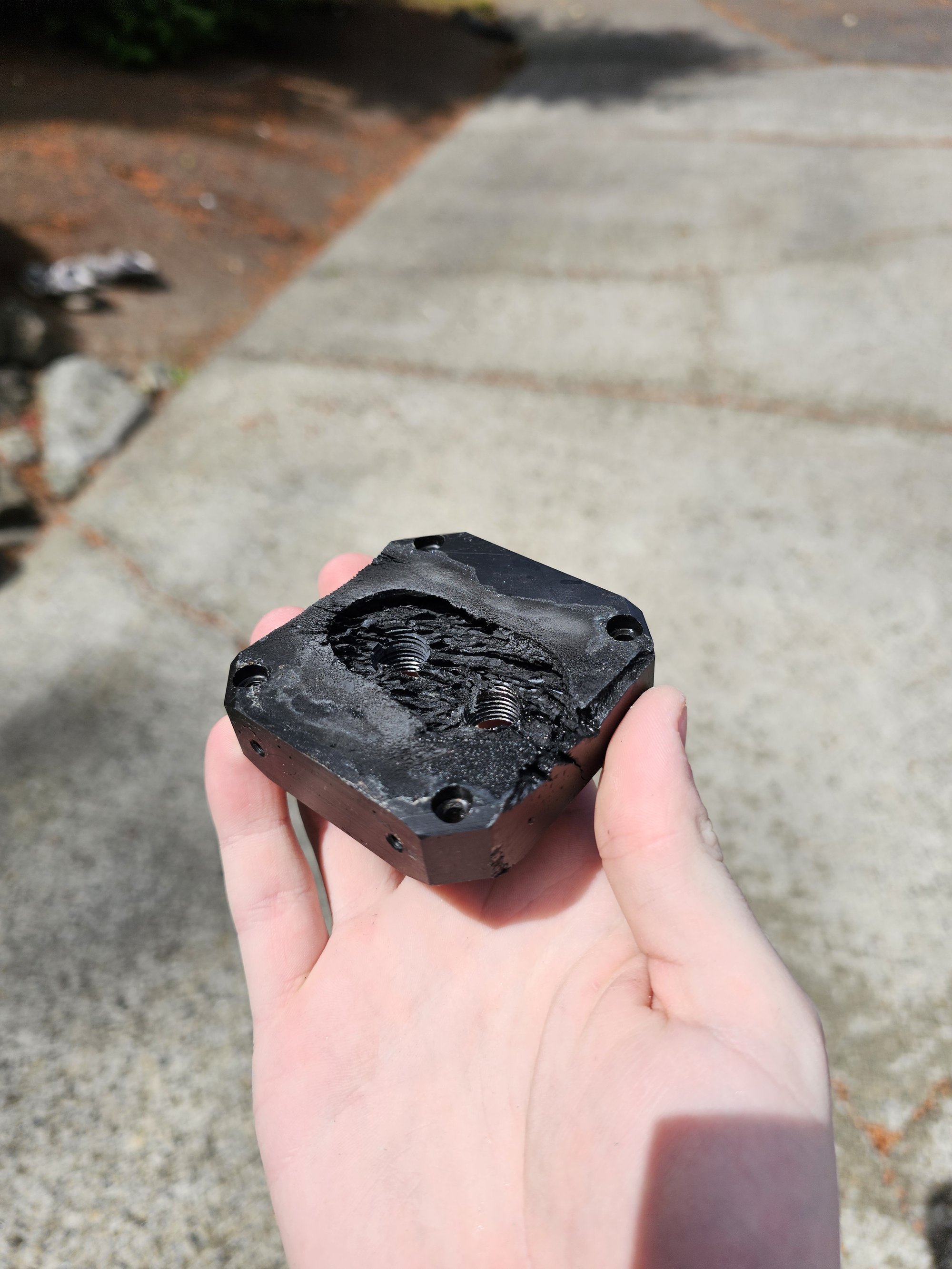
Heatkiller Reservoir Top

Naturally Dyed Coolant
Copper Buildup
Blocks
All the blocks were completely fine. I didn't get pictures of the radiators since it was very hard to see, but they were internally coated in cuprous oxide which unfortunately is a poor thermal conductor, and so I cleaned them out with a 25% dilution of star-san (phosphoric acid + smidge of dodecylbenzenesulfonic acid), which it turns out is phenomenal at removing buildup like this, and cleaning parts in general.
WIP Nickel Removal
Left: Polished. Right: Raw.
Finished GPU Block
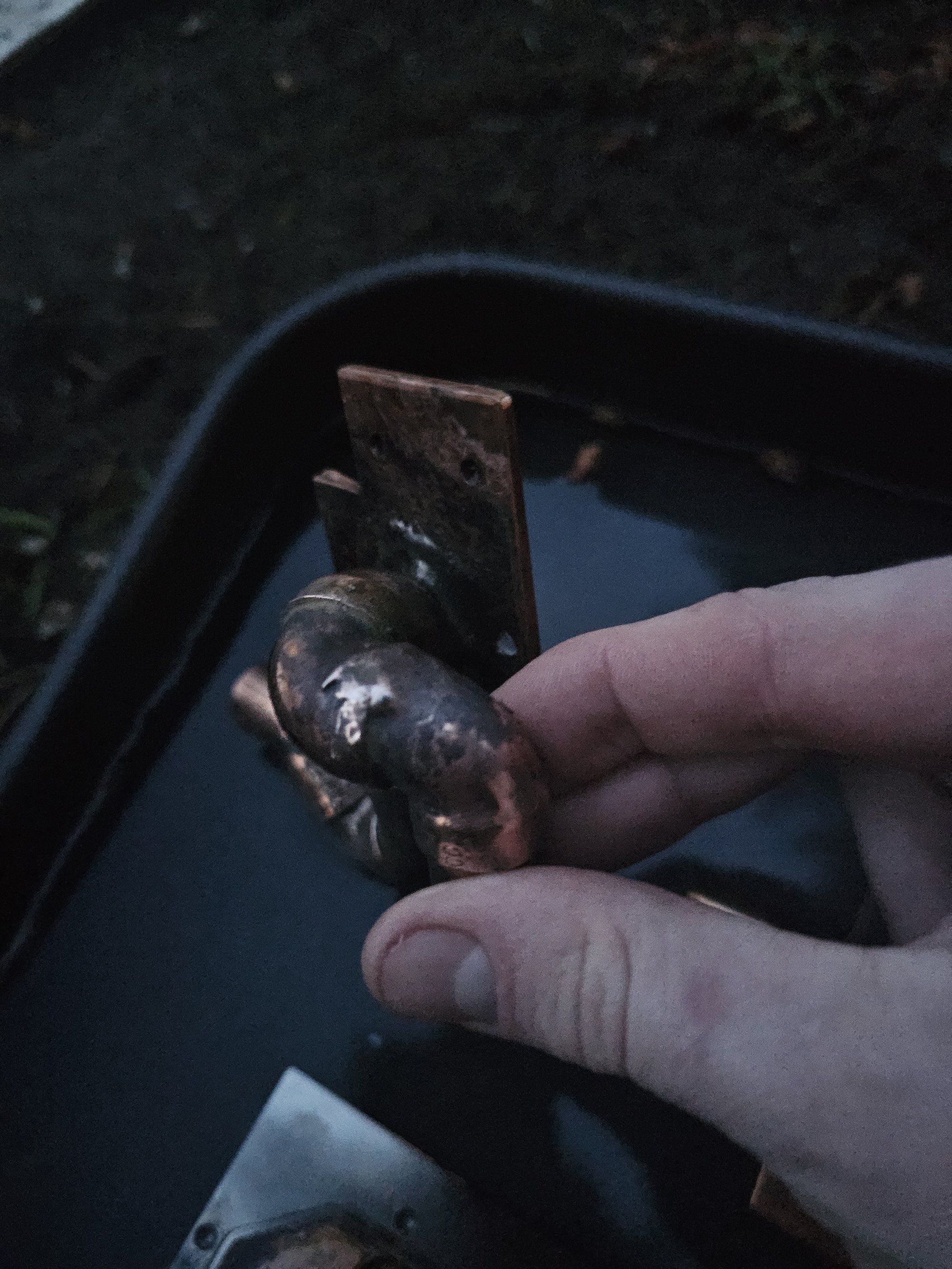
Patched Copper Pipe
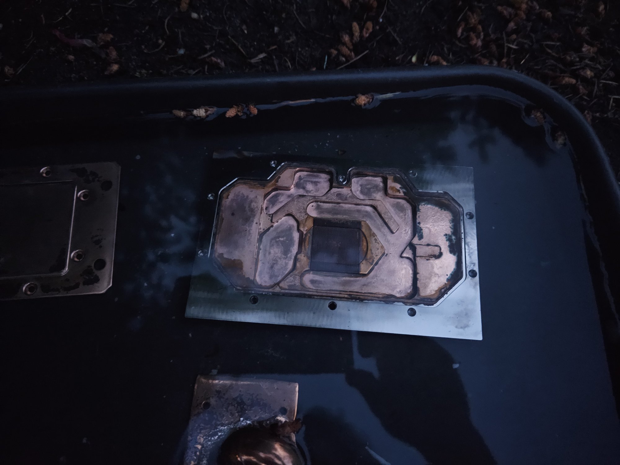
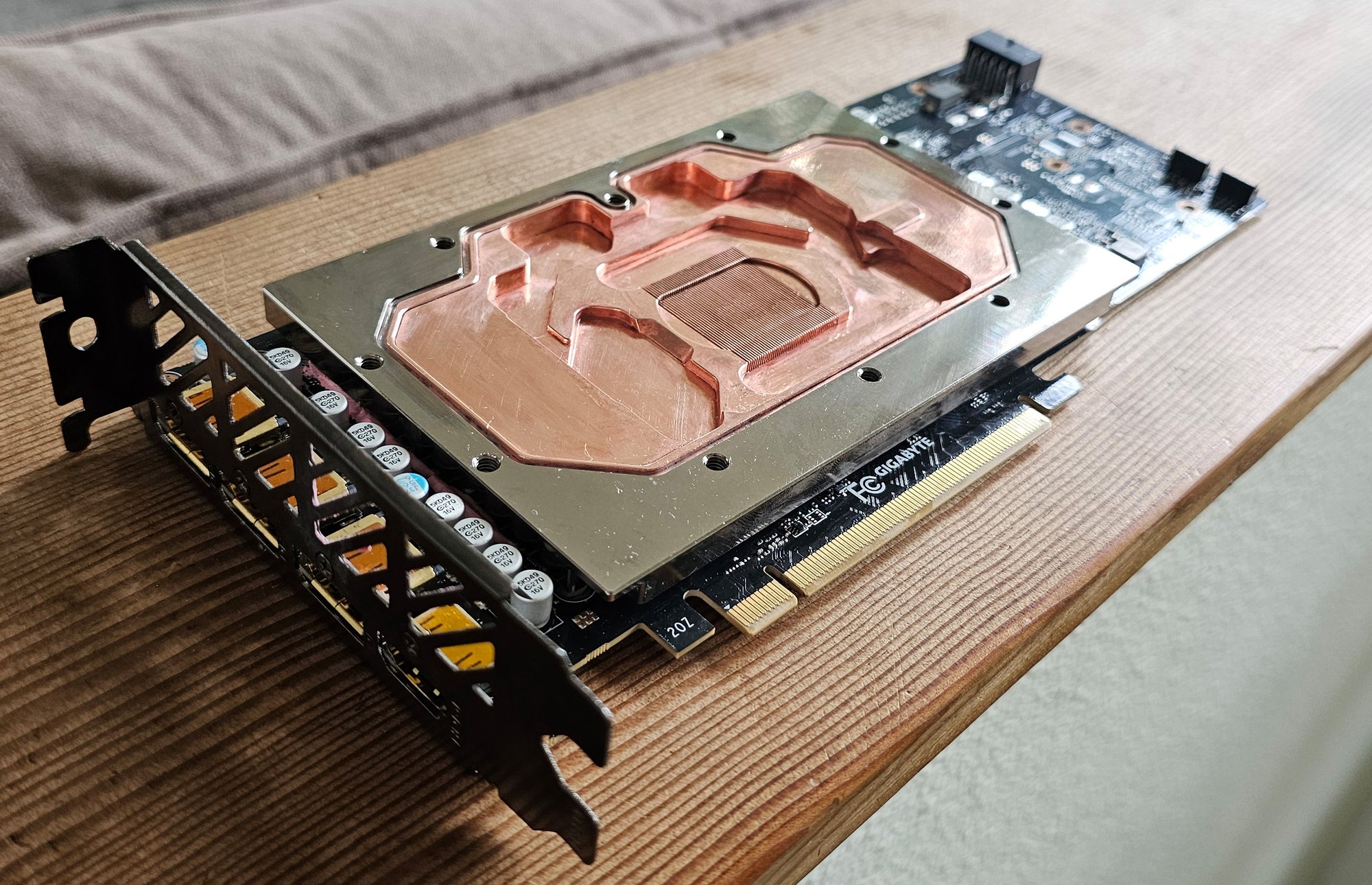
I realized I had been a complete moron earlier when I tried to strip the water-contact area of my GPU block with 37% hydrochloric, and that I needed a fucking oxidizer since HCl is a non-oxidizing acid. I have no idea how I forgot this, since I've been using that exact etchant for years to make PCB's. I used the same 37% HCl along with 50% H2O2 and got incredible results.
I mainly used a pile of cotton swabs, though I used some premium foam swabs for the edges. For large areas I dripped solution down with a syringe to apply enough volume quickly. This etchant obviously eats organics, but not so fast that swabs and paper towels couldn't be used.
warning: This solution (especially this strong) is extremely reactive and actively degenerates and produces a ton of chlorine gas. I was not careful enough about wearing my C4 + CRBNCF50 all the time and ended up irritating the hell out of my lungs between this and the multiple days of star-san use. It took 5 days to realize it wasn't asthma (continually got worse through continued exposure), and another 5 days to fully recover.
Copper Pipe
Patching the copper pipe's pinhole joint was simple enough: scotch-brite target area, preheat, flux everything, overfill + cap. This method is important because it removes reliance on the actual joint seam fully filling back in, which it likely won't as its still probably full of garbage.
I took the opportunity to remove much of the old cuprous oxide from the thermal pad contact areas. I stopped where I did because I was really starting to thin the copper plates down.
I brought them back to a high polish using paper buffer dremel wheels and D5 compound.
Cleaning
Curprous oxide (not to be confused with cupric oxide) was formed from the continuous stripping of copper surface passivation layers, leading to the elemental metal reacting with oxygen dissolved in the water, and thus the release of Cu, Cu+ and Cu+2 into the water - which then comproportionated (Cu + Cu+2 => 2Cu+) and precipitated.
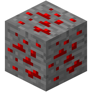
Redstone Ore
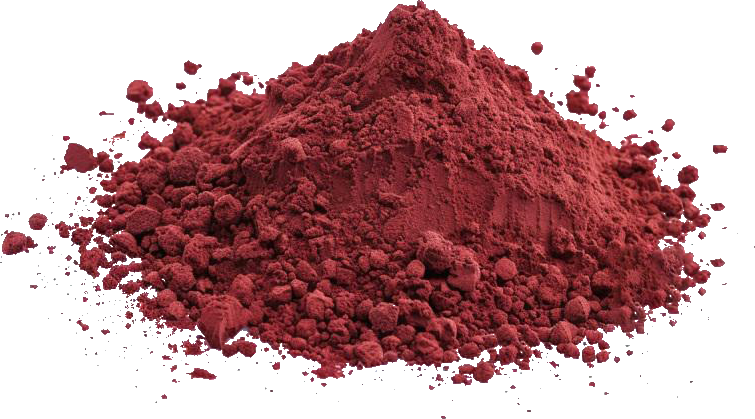
Actual Cu₂O
This cuprous oxide buildup was present in my radiators and fittings. As cuprous oxide is a poor thermal conductor (its a semiconductor too, this is a good tip-off), I had to remove it from inside my radiators and fittings, without damaging them. My primary concern was the black enamel paint on everything, so I needed something that wouldn't damage that. I searched around and found that phosphoric acid would work well without damaging the parts, and I had a bunch of Star-san already. Star-san also has dodecylbenzenesulfonic acid in it (DDBSA) which is an excellent surfactant and catalyst, which helps with uniformity of reaction.
I mixed a solution of 25% Star-san and 75% water. I filled the radiators ~80% full with a fill-bottle and capped them, then shook them in several sessions with ~15 minutes spacing inbetween each shaking. I was able to tell they were clean when the insides around the ports had no red left, and re-flushing with Star-san ran clear instead of blue.
I dumped the fittings into a bath of Star-san and hand-scrubbed them. I dumped non-rotary fittings into my ultrasonic since I wouldn't have to worry about damaging the rotary joints + rings.
Touchups
I got to a few other items while I had the machine apart.
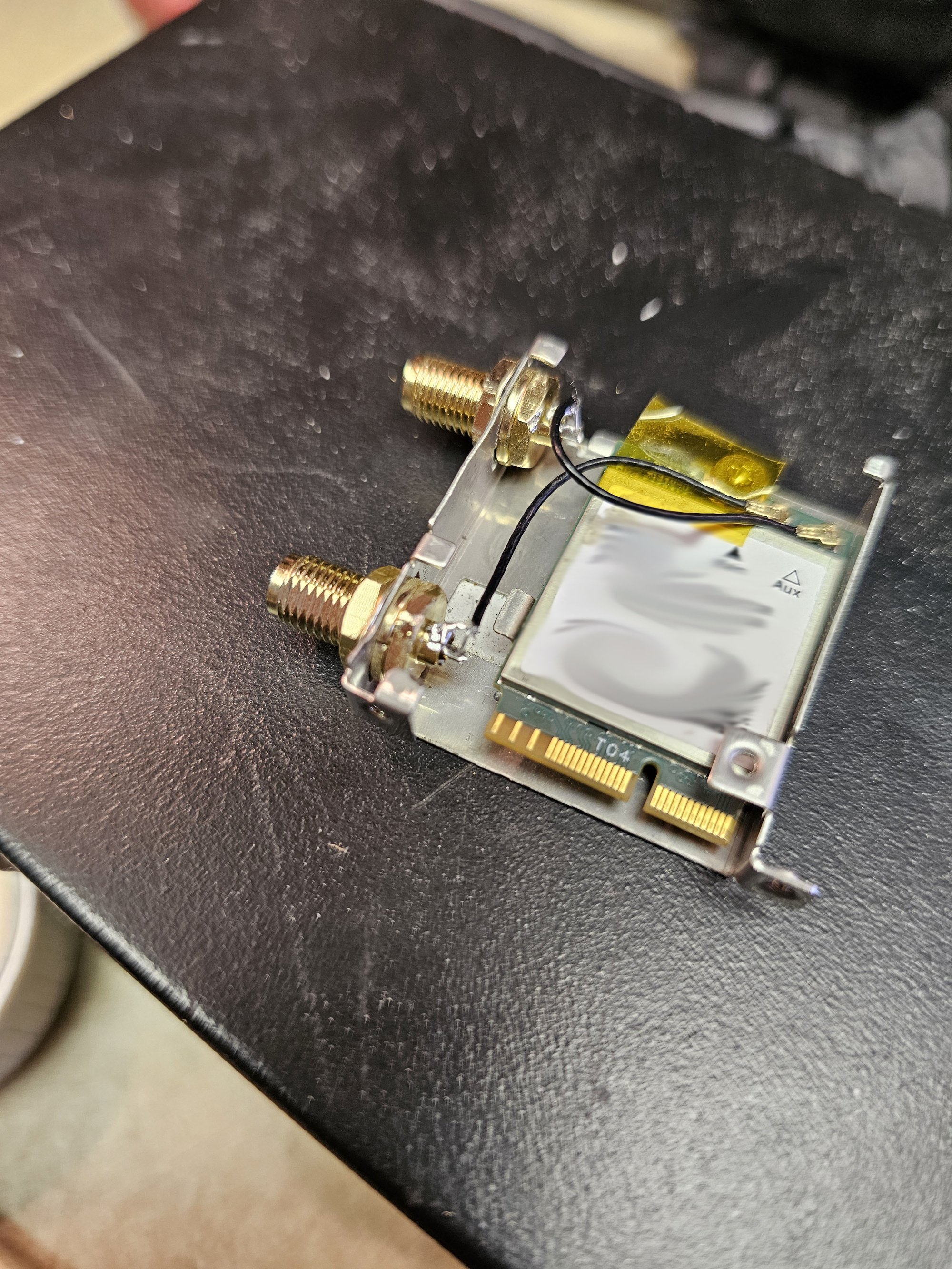
Insert Wifi Name Here
Wifi Antenna
This board came with ASUS's disgusting quick connect wifi 7 piece of shit connectors, and the pin on one connector ended up getting pushed out. I replaced them with normal fucking RP SMA connectors which not only function and are more robust, but make this wifi card compatible with every normal RP SMA antenna, so now I don't have to use the garbage overpriced ASUS antennas with the paper mache connectors.
Kill Coil
I couldn't find my actual kill coil, but I had a bunch of the silver it came from melted down into a screwdriver as a casting test, and you shouldn't waste this stuff. Its mil-spec electrical silver so its pretty darn pure. I wanted to get things over with and I had forgotten to add a large coil before assembling the reservoir, so I melted everything down into a quick cast with my oxy-acetylene torch, and made a shape I could drop in through the G1/4 ports.
Added benefit of this is there'll be no rattling from a lightweight coil.
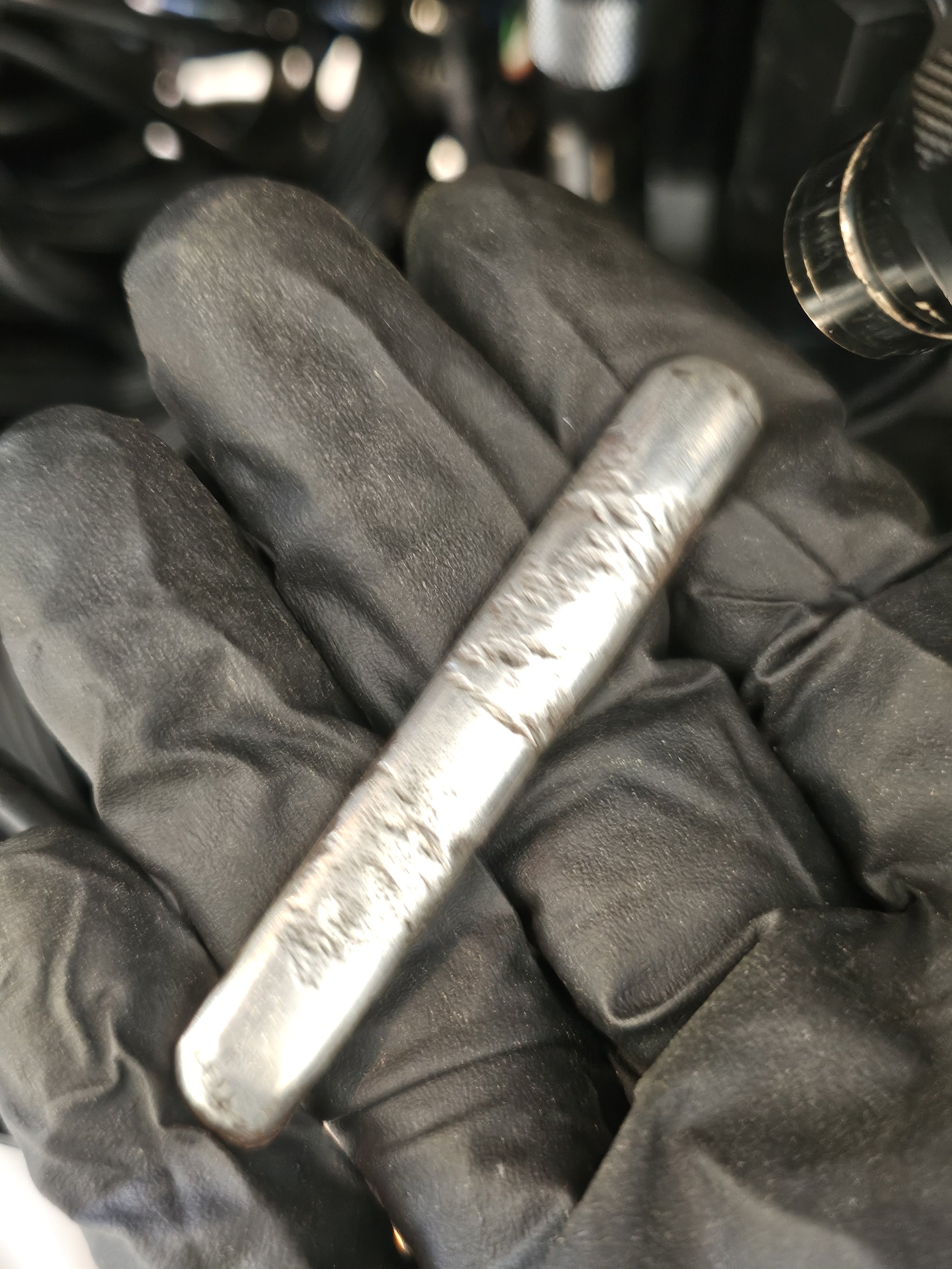
Pure Silver Kill Bar
Threadripper Upgrade
My DDR4 Bdie started dying after ~6 months @ 1.56v even under watercooling (iirc never passing 50C). It exhibited death throes via very rare WHEA errors, where even a 24 hour stress test could run without issue. To solve this permanently I decided ECC RAM was the best and only option. I could have installed a kit of unbuffered ECC RAM into my existing 9950x system, however unbuffered ECC with high clocks and tight timings does not exist. Also, unbuffered ECC is faster in theory on paper, but in reality stresses the memory controller more, so one is limited on capacity and speed there as well.
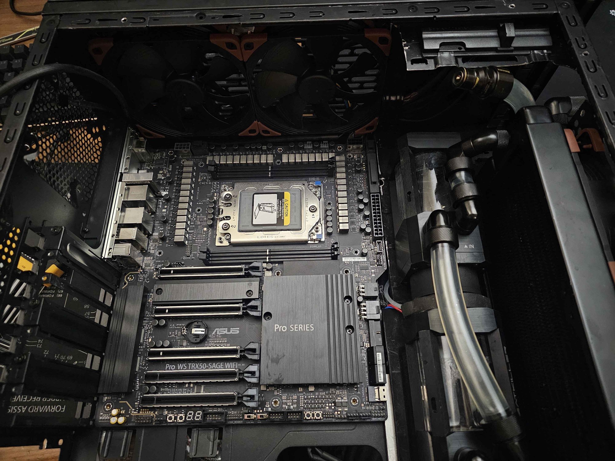
At time of writing, TR5 is good for one more generation after the 9000 series. I went with an ASUS Sage TRX50 (rev1) because its the narrowest TRX50 board (and its ASUS), yet I Still had to modify my case to fit the CEB board profile. I swapped out my venerable Azza (OEM: Superflower) 1000w Platinum PSU for a Superflower Leadex VII 1200w to save on cable adapters (12VHPWR, multiple CPU8's etc.) and because the CPU + GPU alone is 800w+. Going with 6000CL30 to not stress FCLK while maintaining latency.
Power Draw Update: CPU benches at 440w. 4080 Super max recorded: 380w (swapped vbios). RAM benches at 8w per stick.
TODO
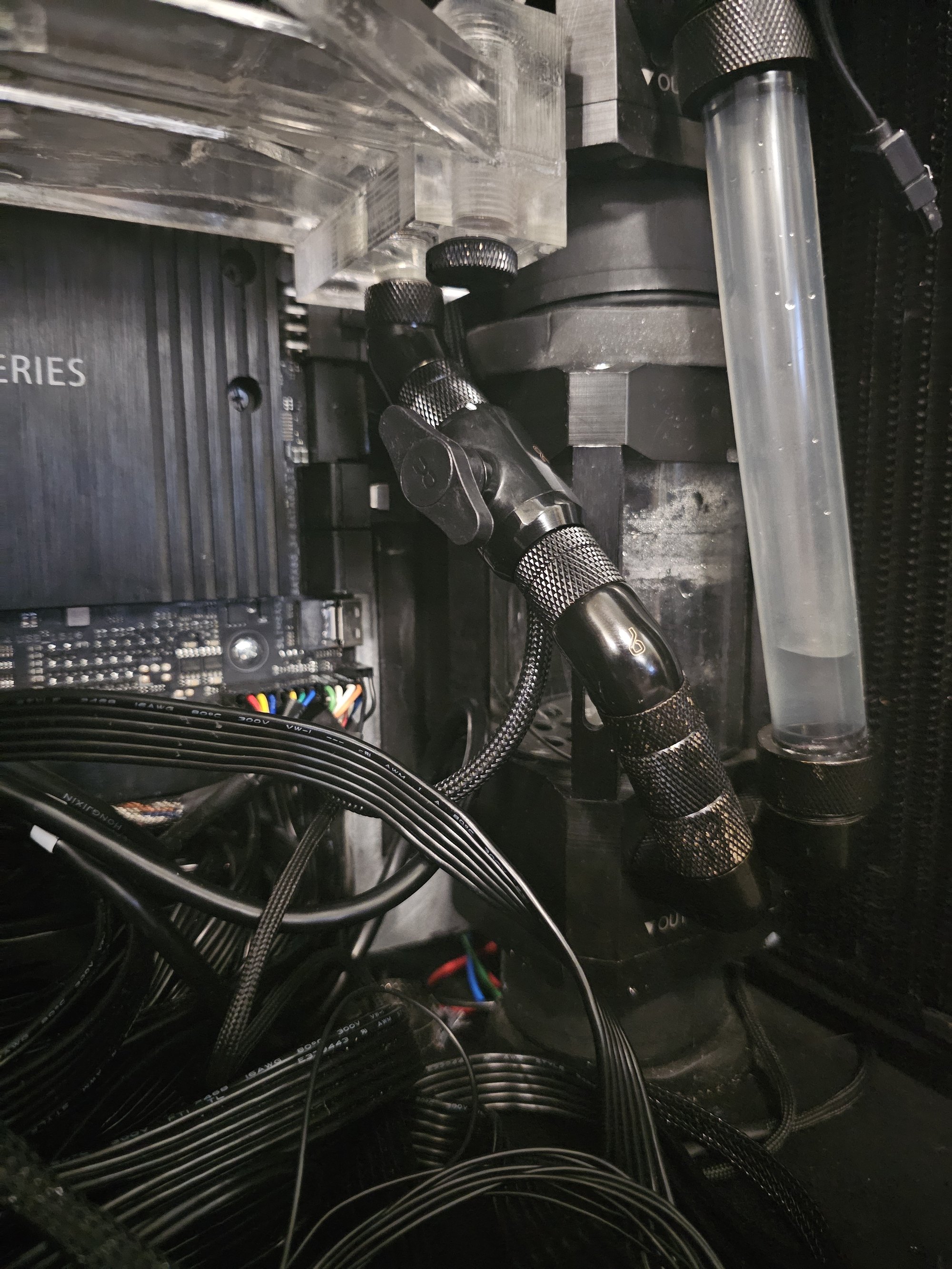
Was put off like many by the idea of "D Plugs" from Alphacool, also didn't think too much about the shape of my new brazed stuff beforehand. At some point I'm going to replace the hoses to / from the CPU and the GPU with D plugs so I can fully service the PC without yanking on poor G1/4 threads. This will pair nicely with my ball valve and purge method.
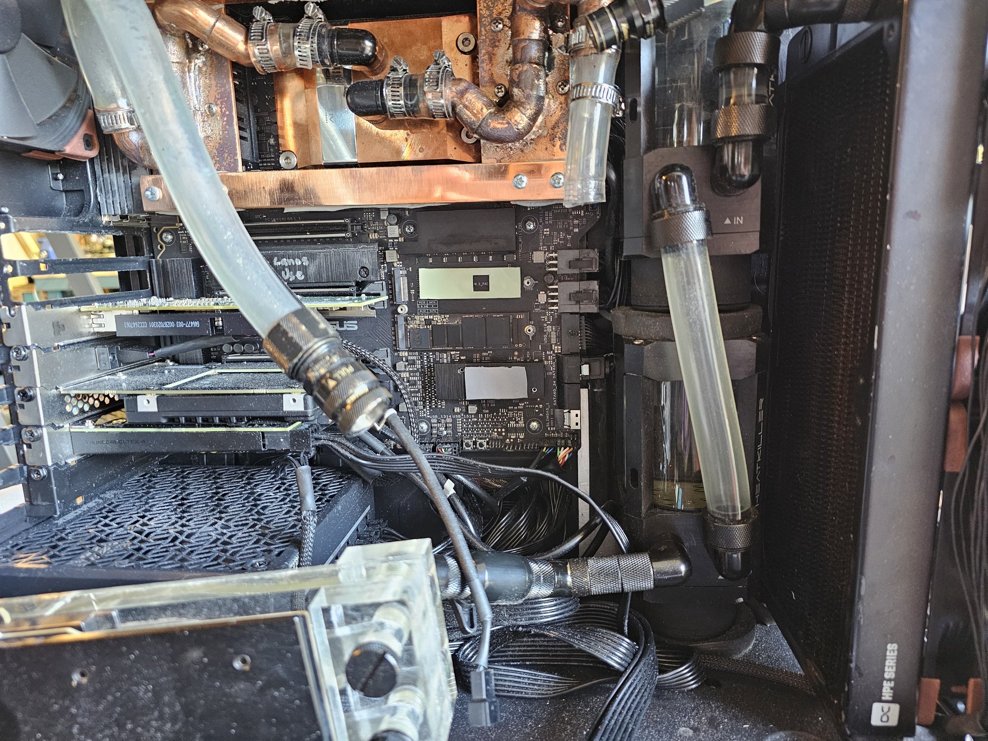
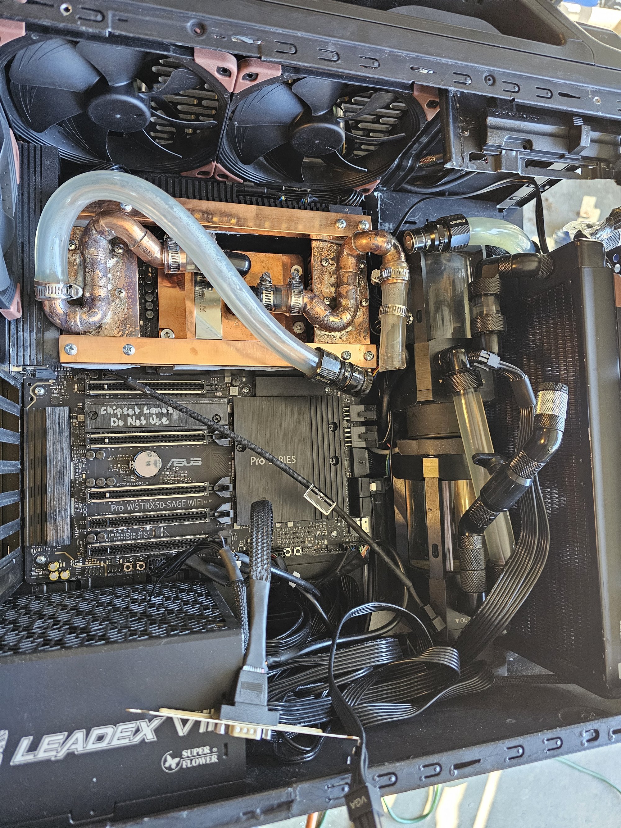
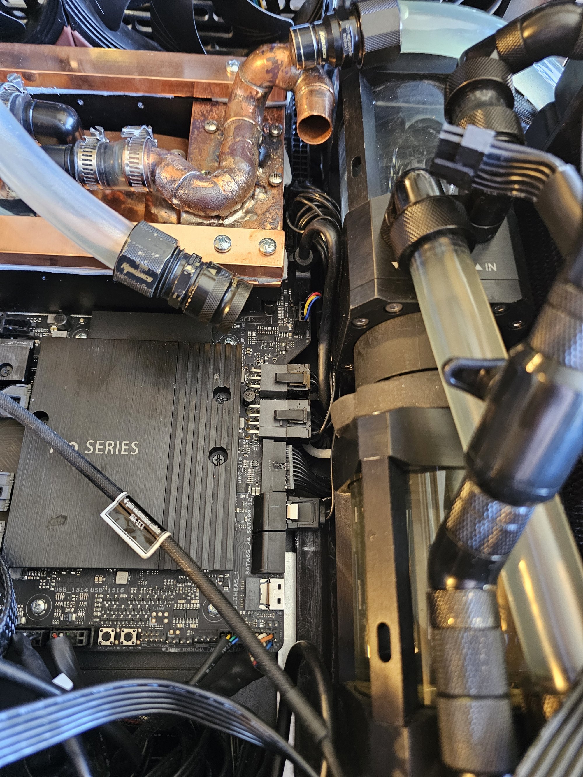
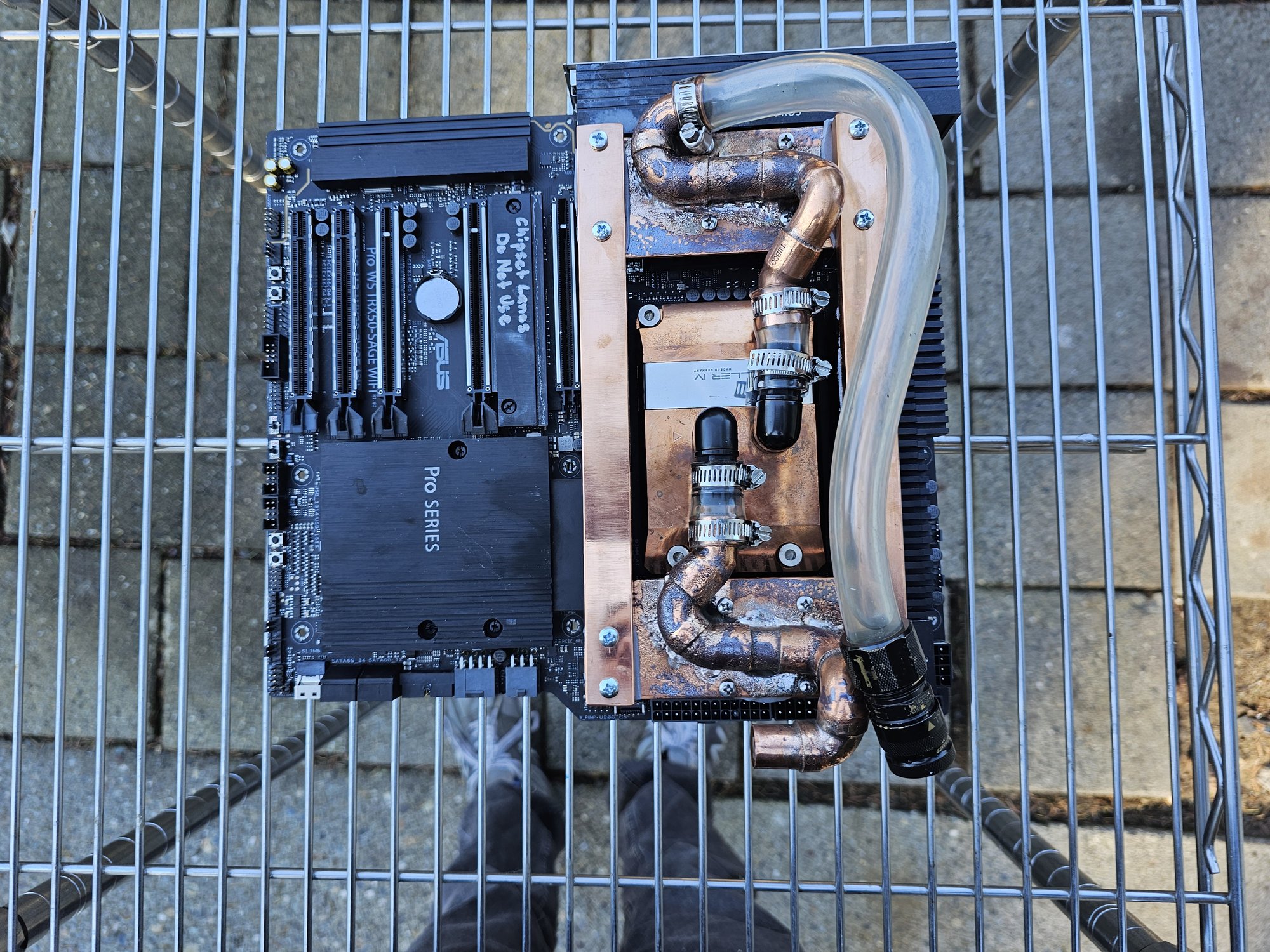
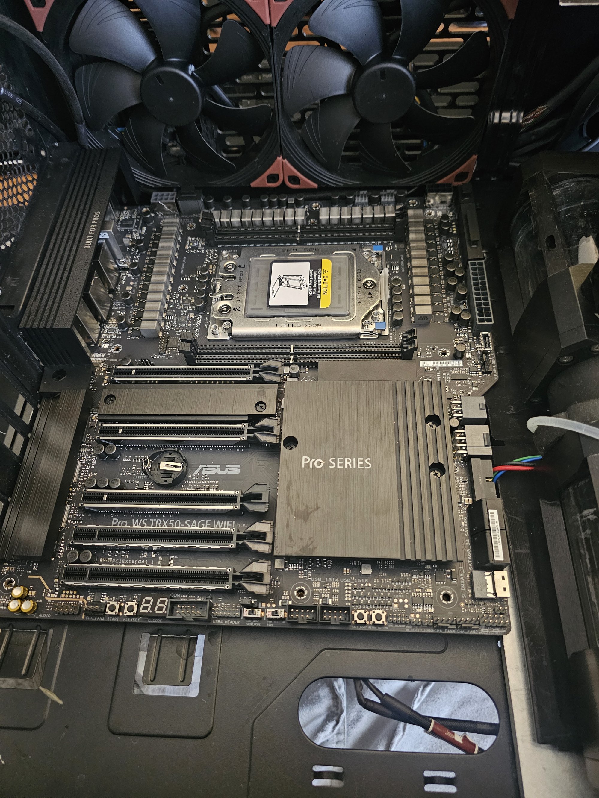
CPU Block
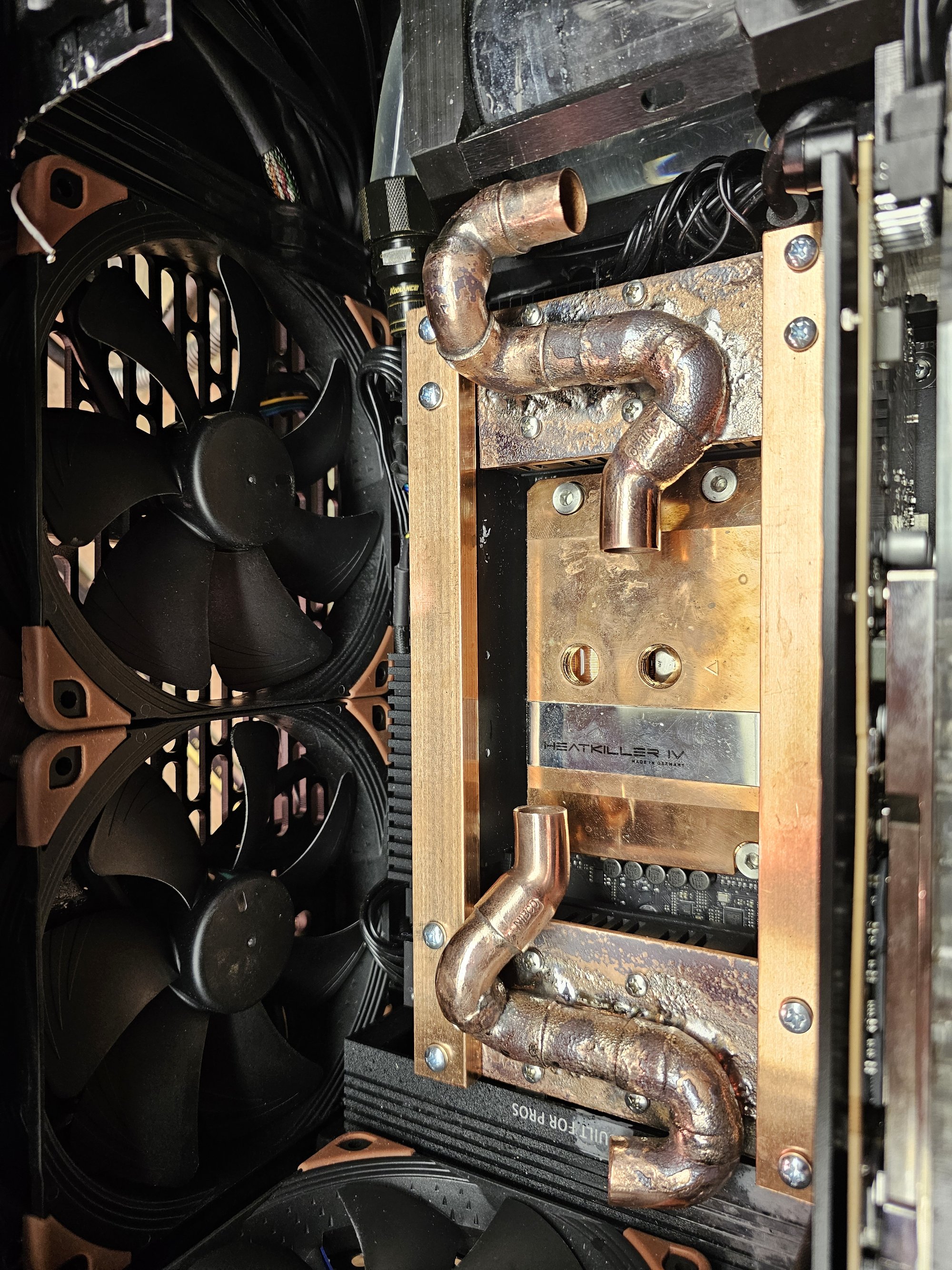
I completely forgot about Optimus, so I bought a Heatkiller IV Pro. The only thing that manages to throttle the CPU is AVX512 synthetic loads. This brings the clock down to 5.025Ghz. Otherwise, the chip stays around 88C up to 440w.
The Heatkiller block had tactile machining marks on the coldplate, and I scratched it. I chose to hand sand it smooth and polish it. I employed the standard lapping technique and hand sanded carefully to conform to the convexity of the coldplate.
Post Code Mod
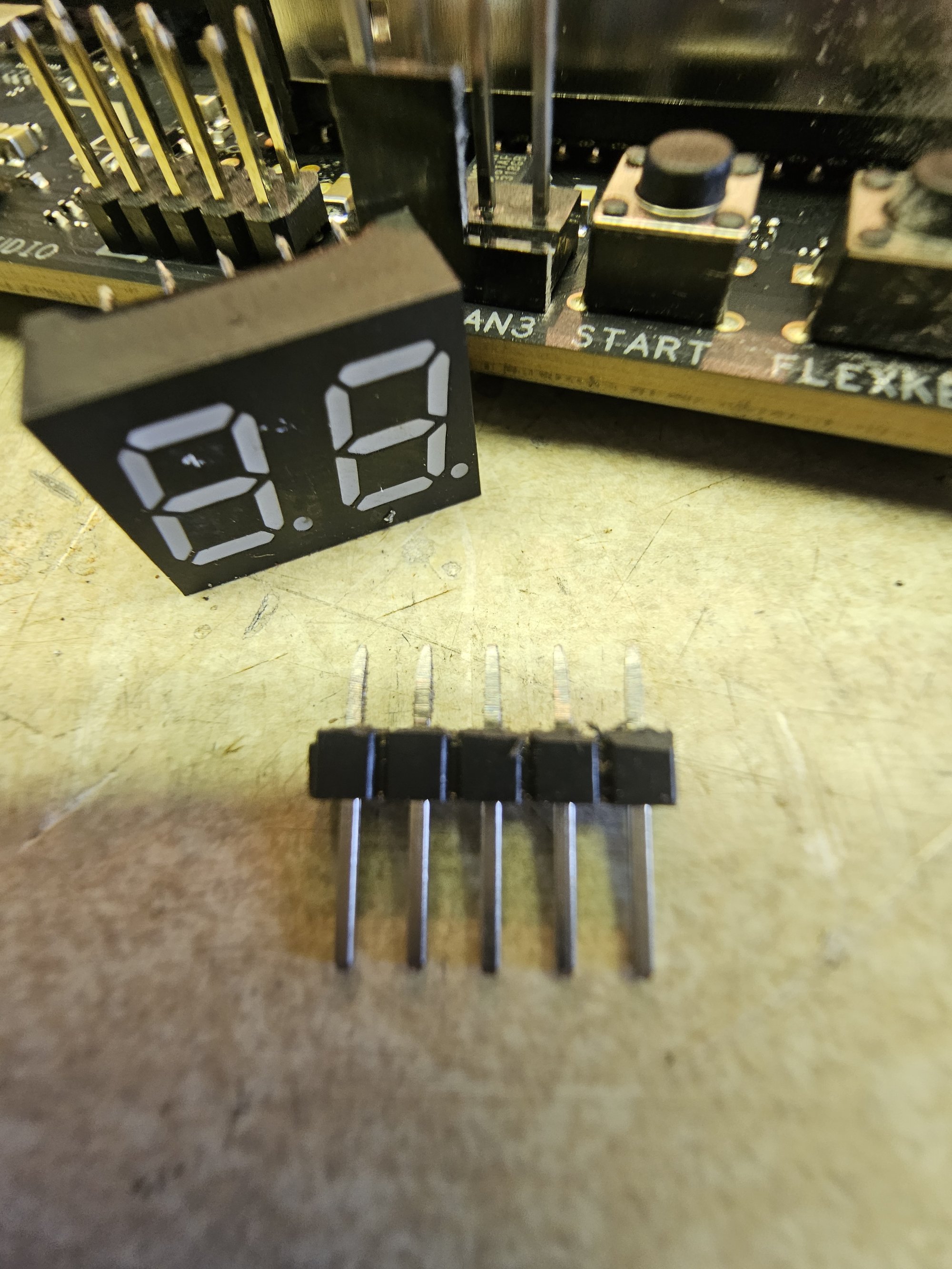
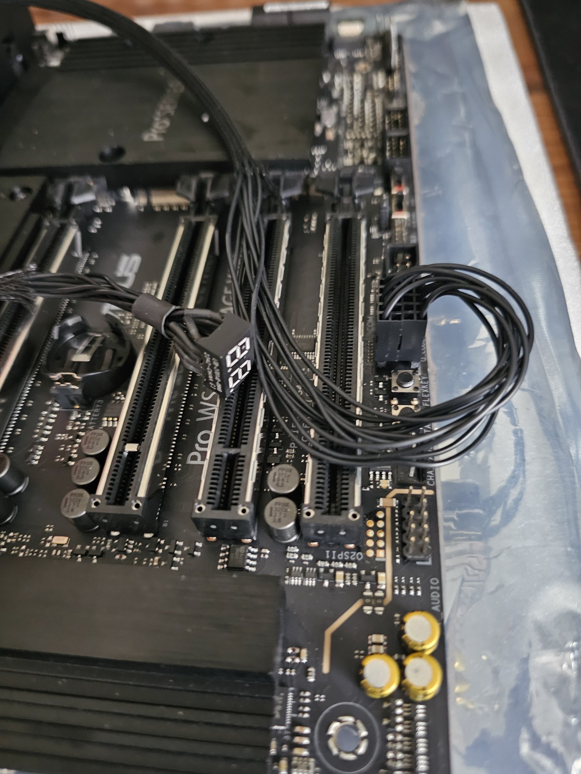
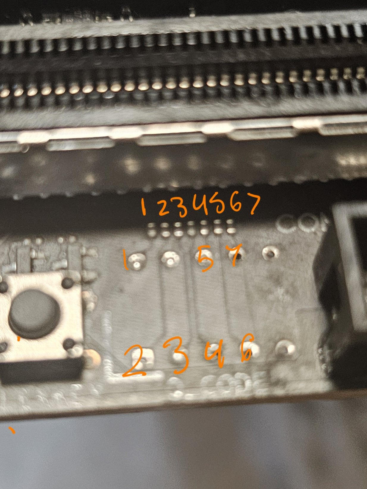
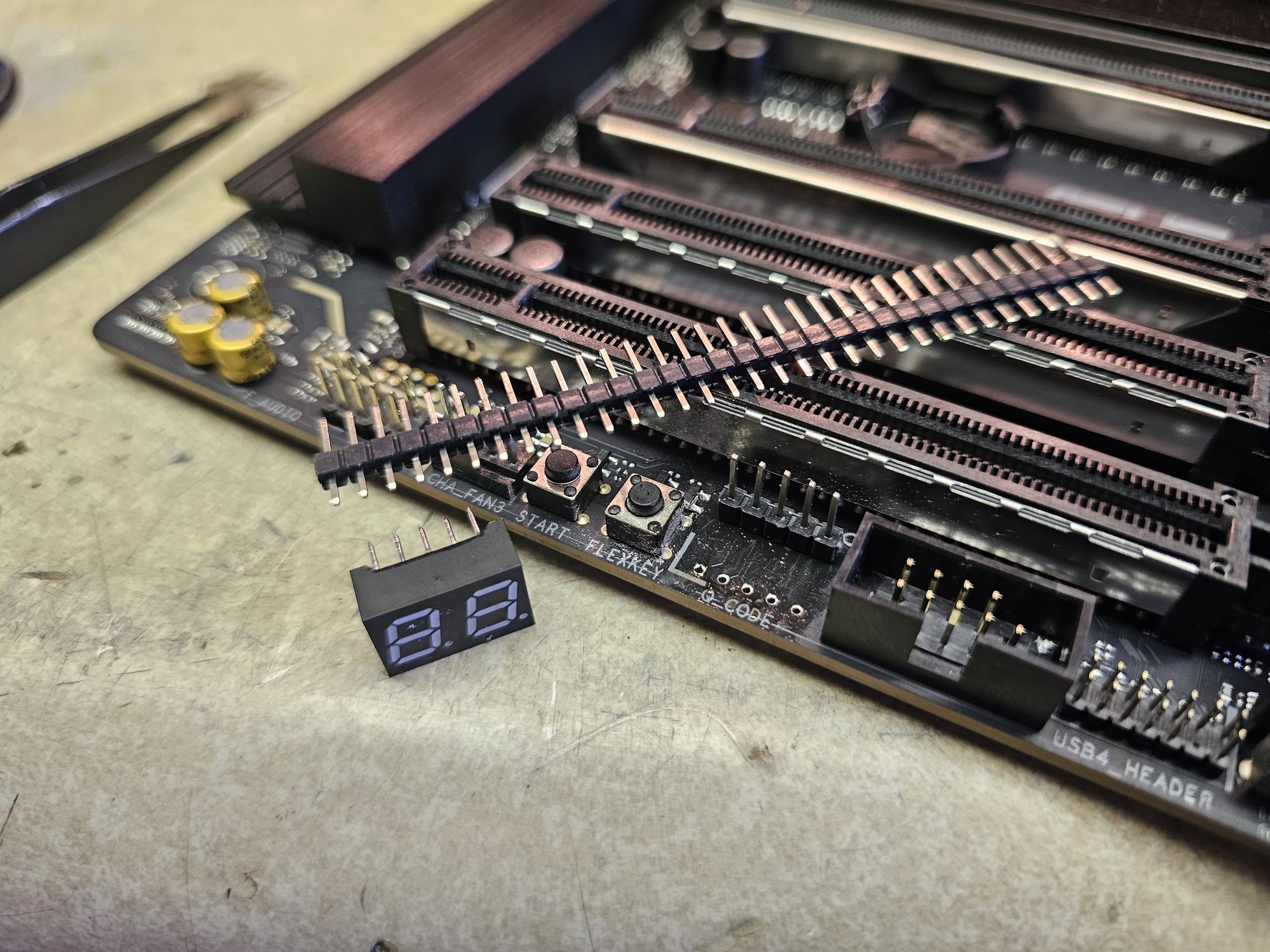
I like the TRX50 Sage, I don't like the postcode location. I noticed the pin spacing on the 7 segment display looked like the dupont spec, and it turns out I was right. A "5x4" dupont connector (glued 5x2 connectors) works perfectly here. I used a mini file to thin the header pins out so they were thin enough to slide into the boards vias.
This worked perfectly the first time, and then my board was DOA. The second time I was a lot more strung out, and wrecked something somewhere on the board or most likely in the display matrix, since now one segment gets routed to the wrong LED. This is apparent because postcodes are still more or less decipherable, and I can see that when the missing segment should be firing, its neighbor is twice as bright as it should be.
It ended up not mattering much because the display is so bright I keep it taped off with foil unless the machine isn't posting for some reason. IMO this was still very very worth it. It is incredibly nice to be able to see the postcodes while sitting down.
Ram Heatsinks
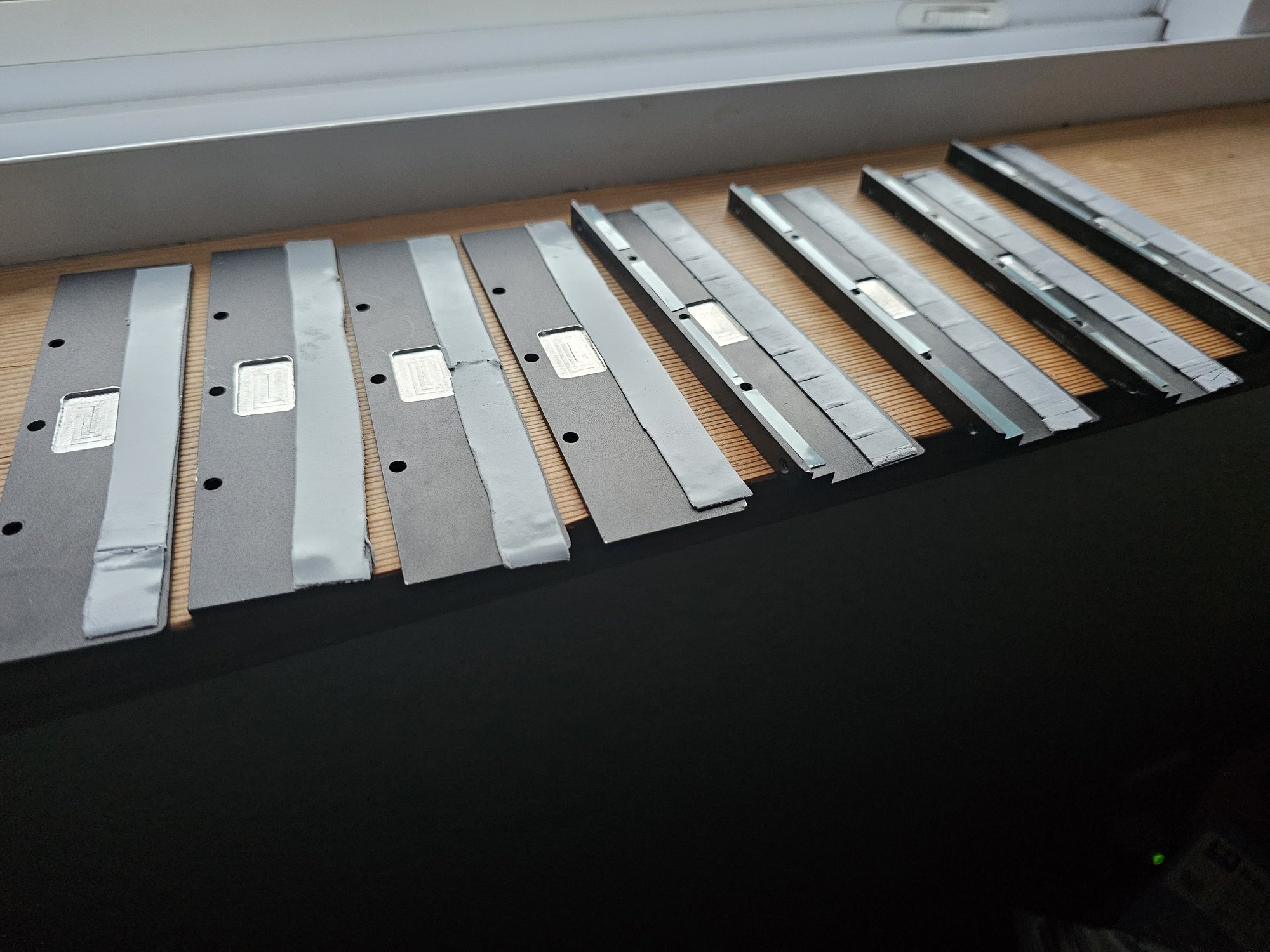
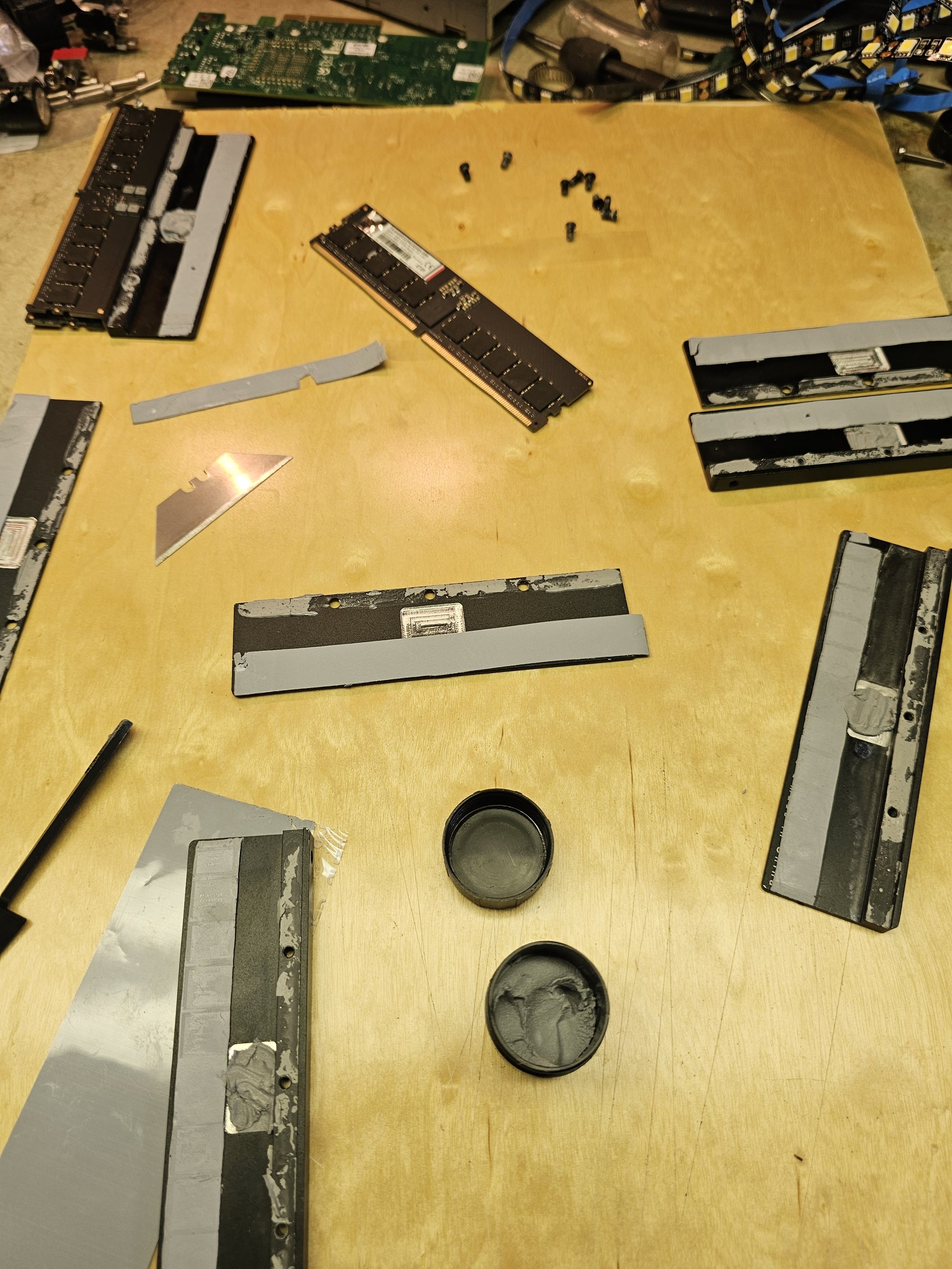
The RAM heatsinks had to be modified like "usual" with pocketing (see Dreanought project). I went for double sided pocketing here because the caps on the backsides of these new sticks I have get uncomfortably close with 0.5mm pads (which alphacool seems to know, since the heatsinks came with a single spare thicker pad strip). Again because of time. I went with this instead of something nicer like solid copper heatsinks machined from scratch (which I have a clever design for). I used PTM7950 to interface the fins to the spines of the heatsinks and not grease because its a lot less messy and I had a bunch of scraps.
UPDATE: I THINK I might have been cooking the PMIC's. Being in an aluminum pocket coffin might get them too hot, so I filled the pockets with TG Pro thermal putty. I also replaced the PTM7950 fin filler with putty. 2 of my kits died and this third one is going strong.
UPDATE 2: I am certain this is what was happening. I've seen a good many other such cases now, and NorthwestRepair has a video on reflashing RAM PMIC's and SPD data. It seems like these things are fragile.
VRM + RAM Loop Integration
I went back to the drawing board while my RAM kits underwent RMA.
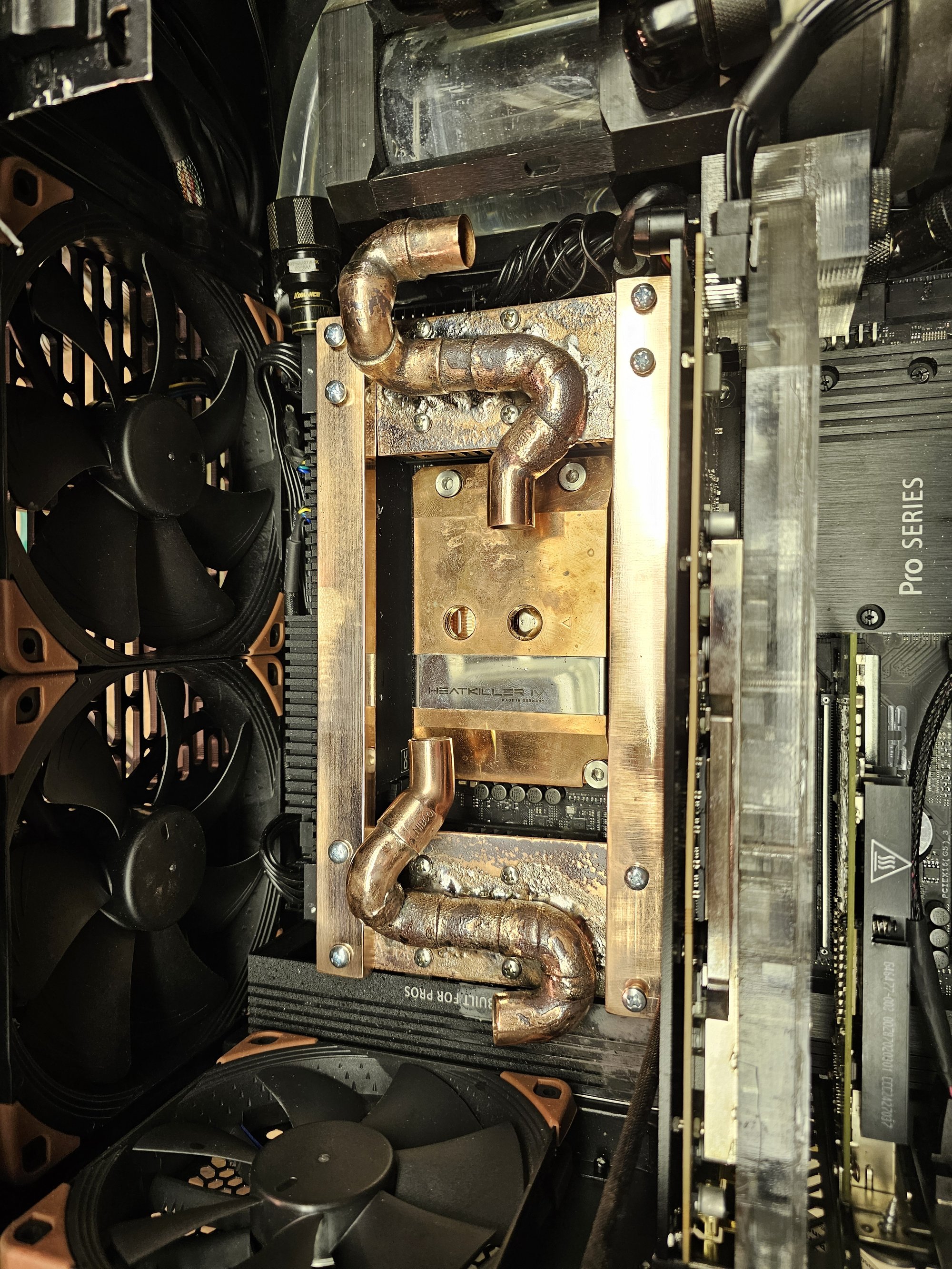
I realized that the RAM was generating little enough heat and I had lottle enough money to cheat and conduct heat down solid copper with enough cross sectional area to be viable. This would allow me to remove RAM sticks without ever touching the loop.
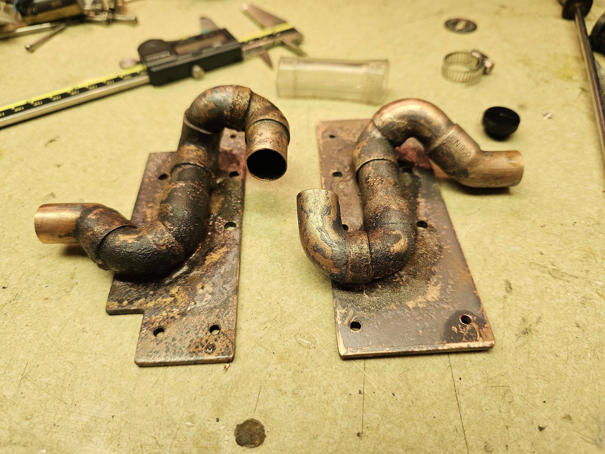
I reused my copper blocks from the noodle for some extra oomph on the VRM heatsinks. They're puttied not brazed to the new copper plates because I gain nothing by brazing them and I can't be fucked.
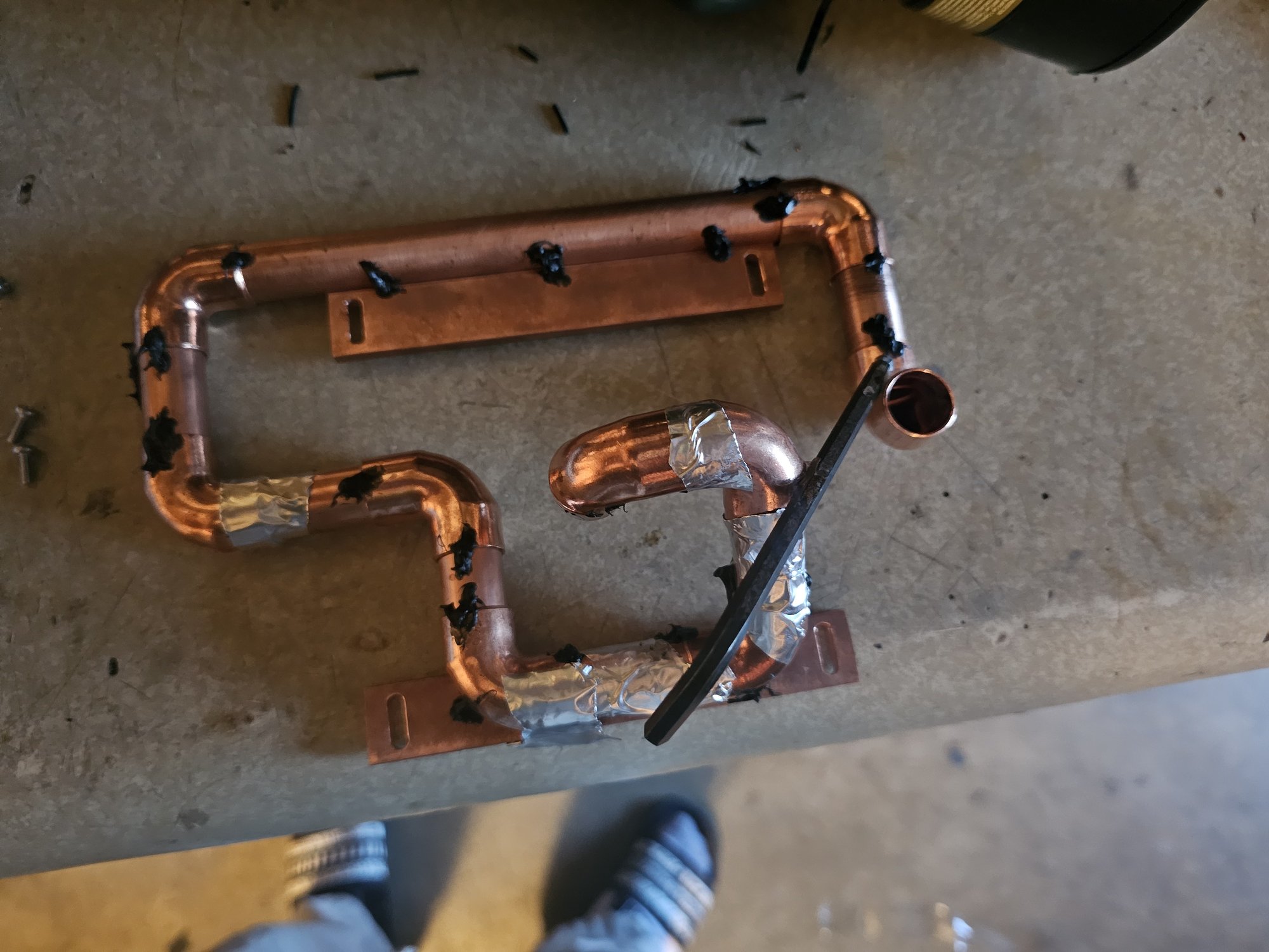
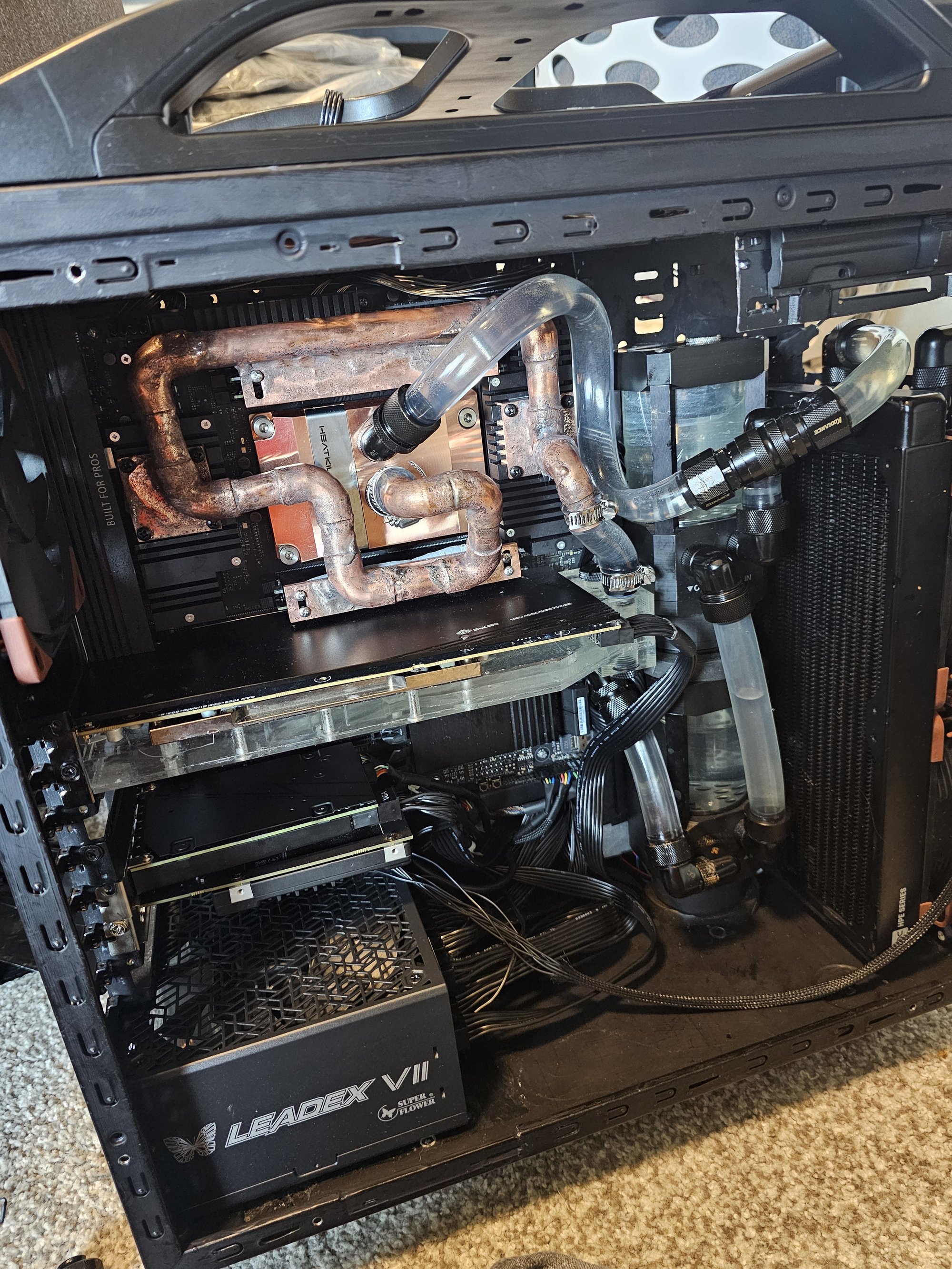
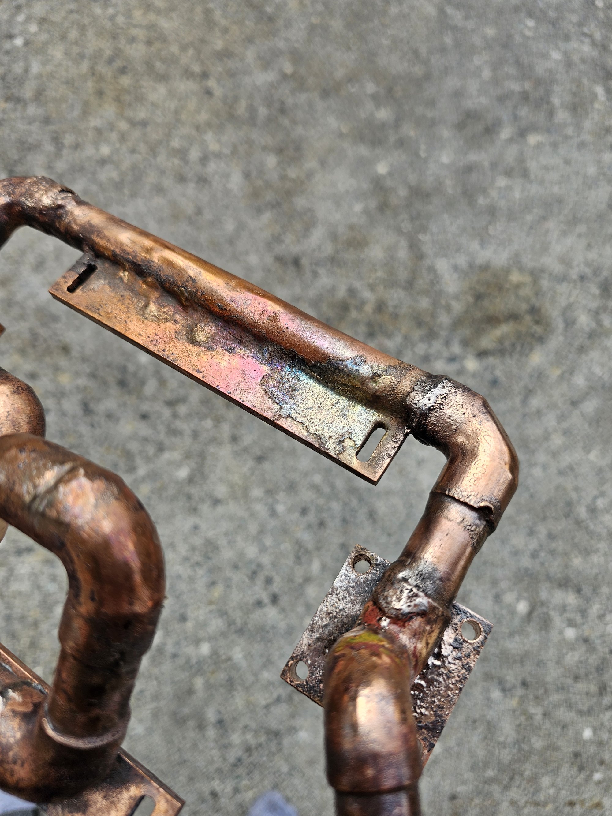
The "tolerances?" for these new mini-noodles is very, very tight. Here's how I brazed these in an evening: slap beads of thick/medium starbond cyanoacrylate around each joint and accelerate to cure, dump glue on the baseplate and stick assembly on. Soaked rags and a size 0 or 1 (yes 1 works) tip aimed carefully and very VERY close to the material and tack braze each joint. After working around you'll find the fully tacked assembly wants to lift off the baseboard because the glue failed, thats fine. it'll still resposition against glue ridges very closely and you should be able to see the imprint of where it was. Tack the assembly to the baseboard, then start working around to each joint and braze them fully. Finally, come back to the baseplate and flambe the shit out of it to get it up to temp for deep flood brazing (you DEFINITELY want a size 1 torch for this step).
The whole trick here is carefully building up more heat tolerant connections such that you don't ruin any positiong and can eventually do the super hot stuff.
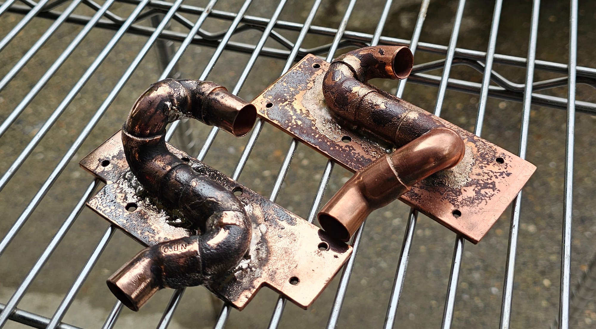
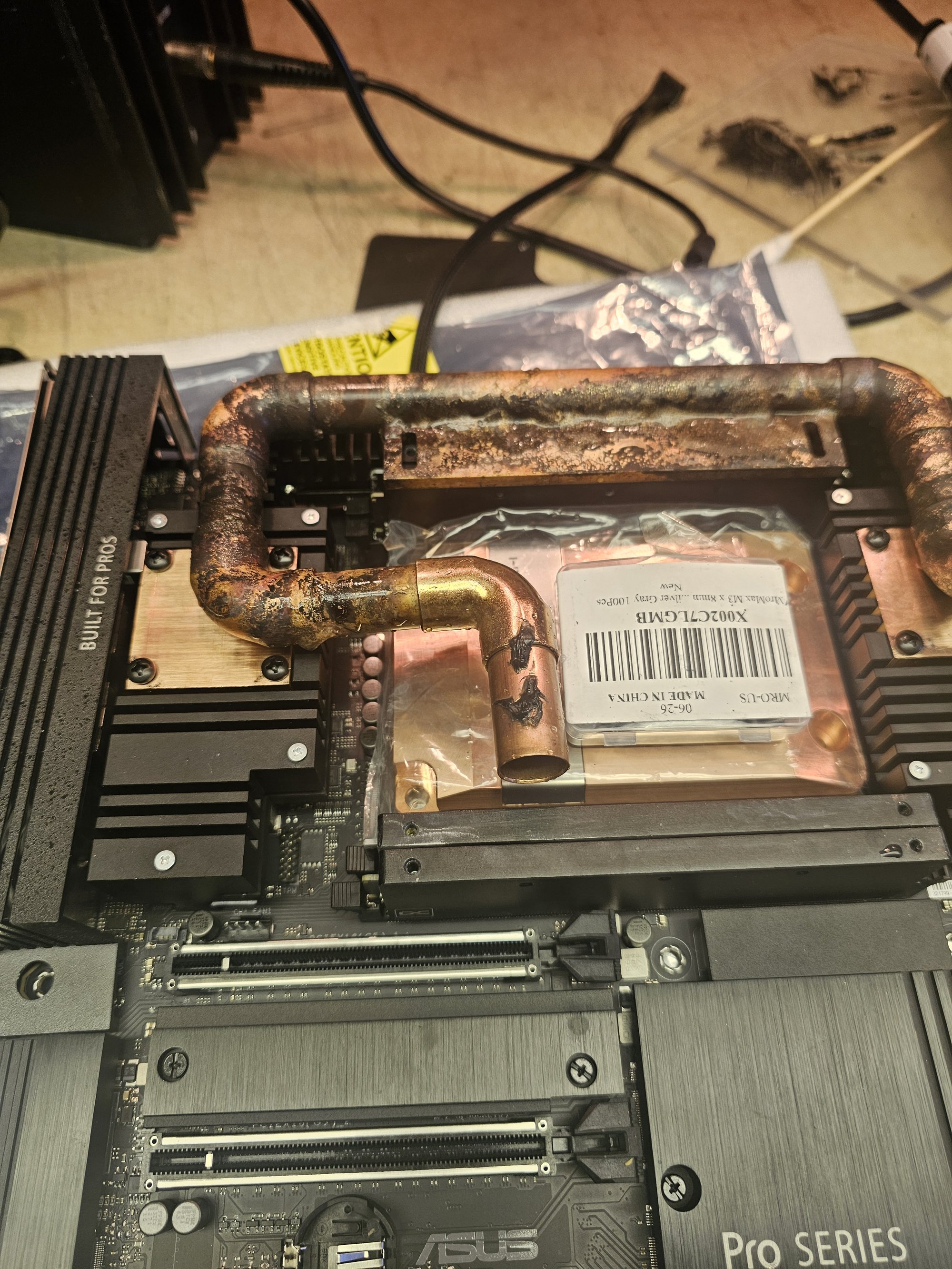
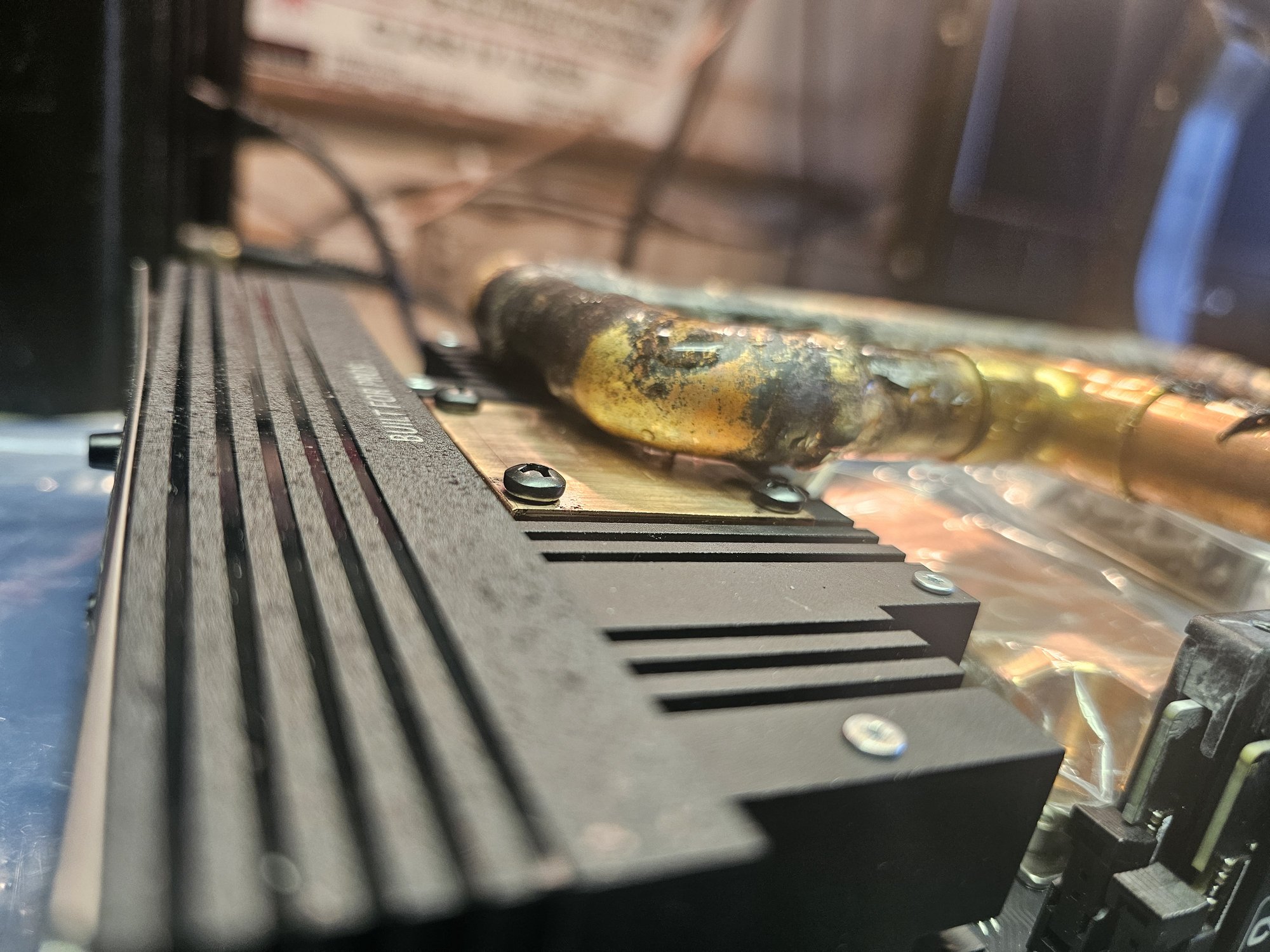
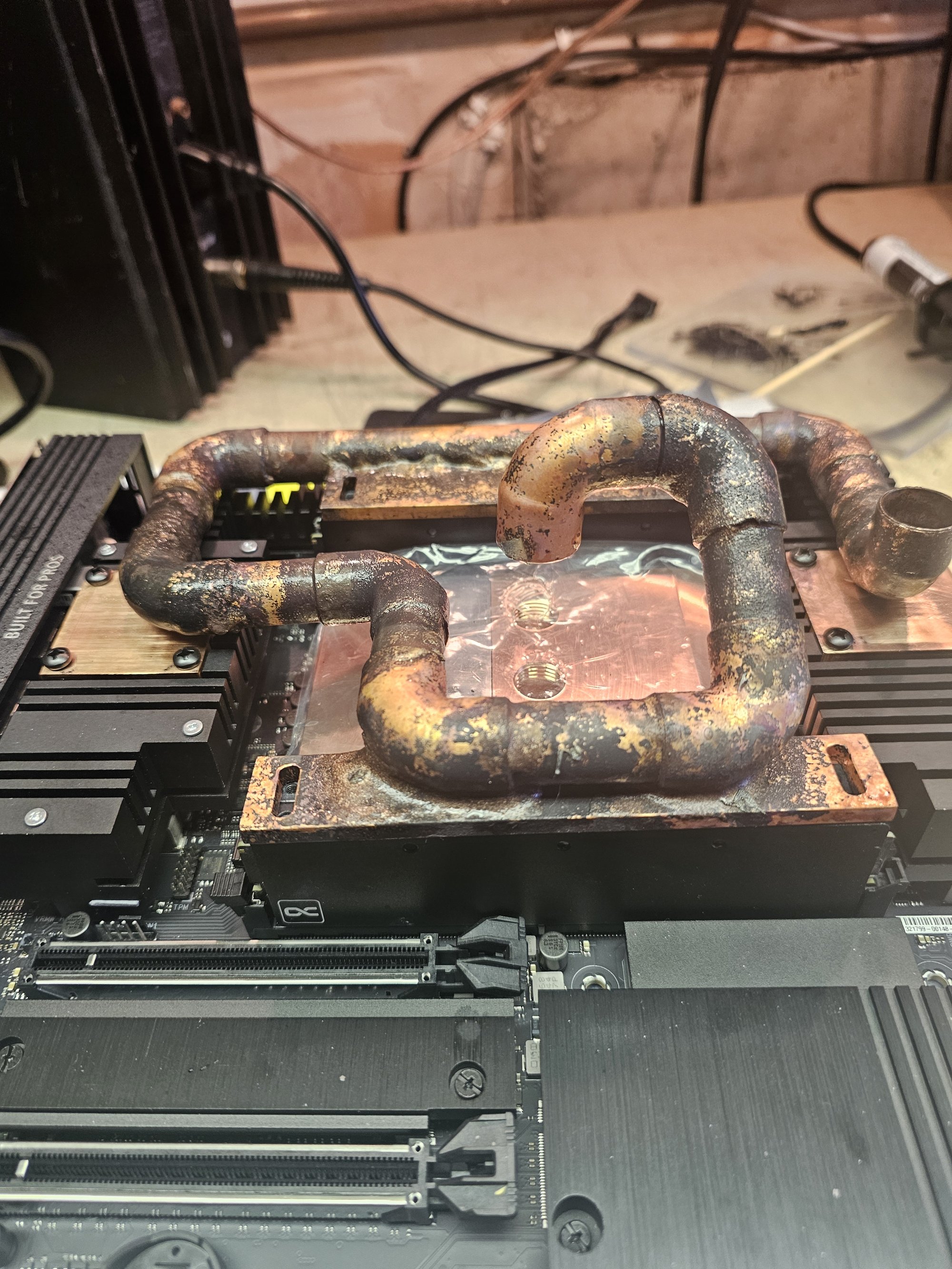
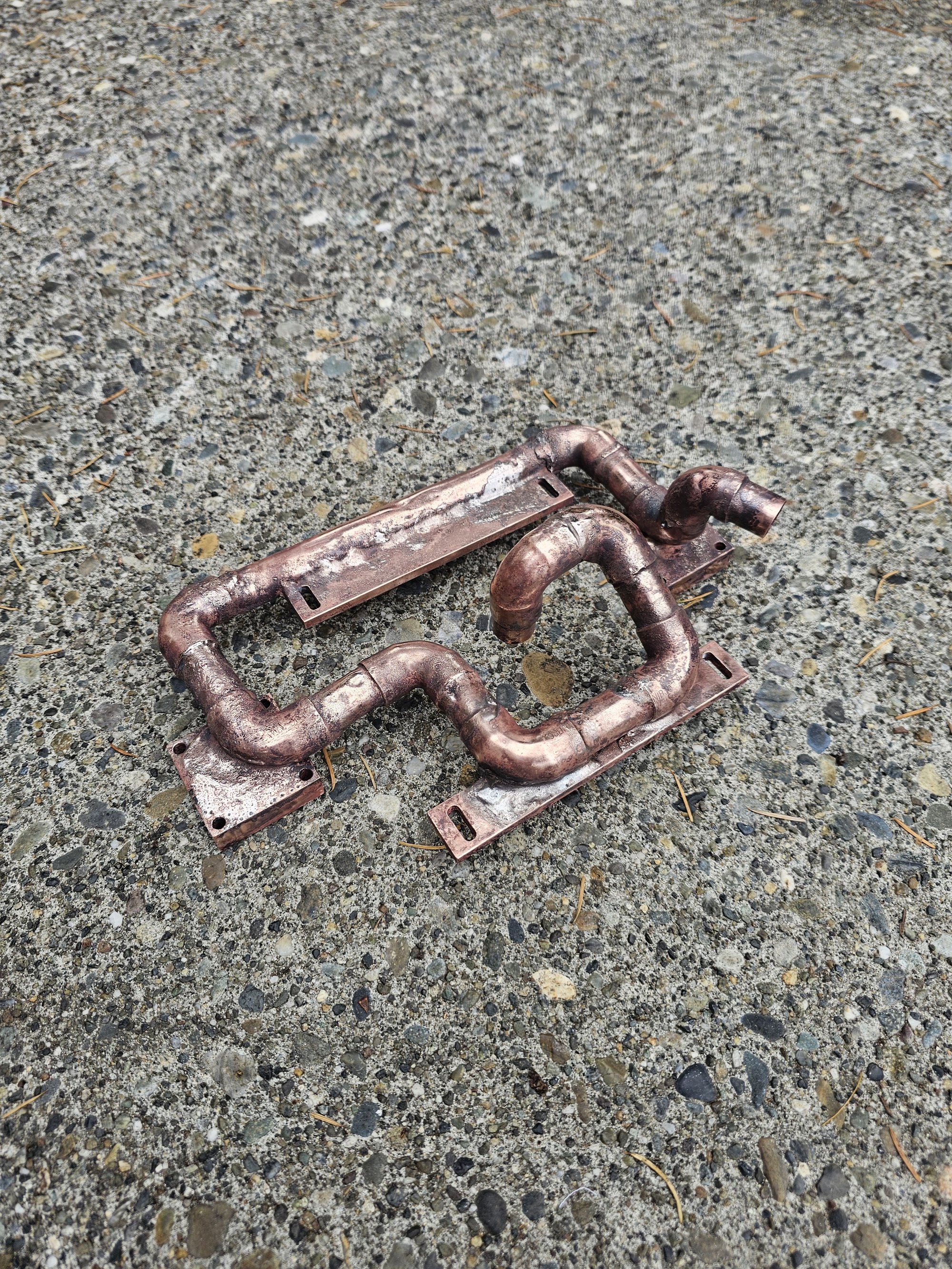
They may look dirty and rough in the pictures from the cuprous oxide but they are polished so insanely hard they're slicker than snot (will slip around like they're drenched in oil). The undersides of the baseplates were surfaced flat.
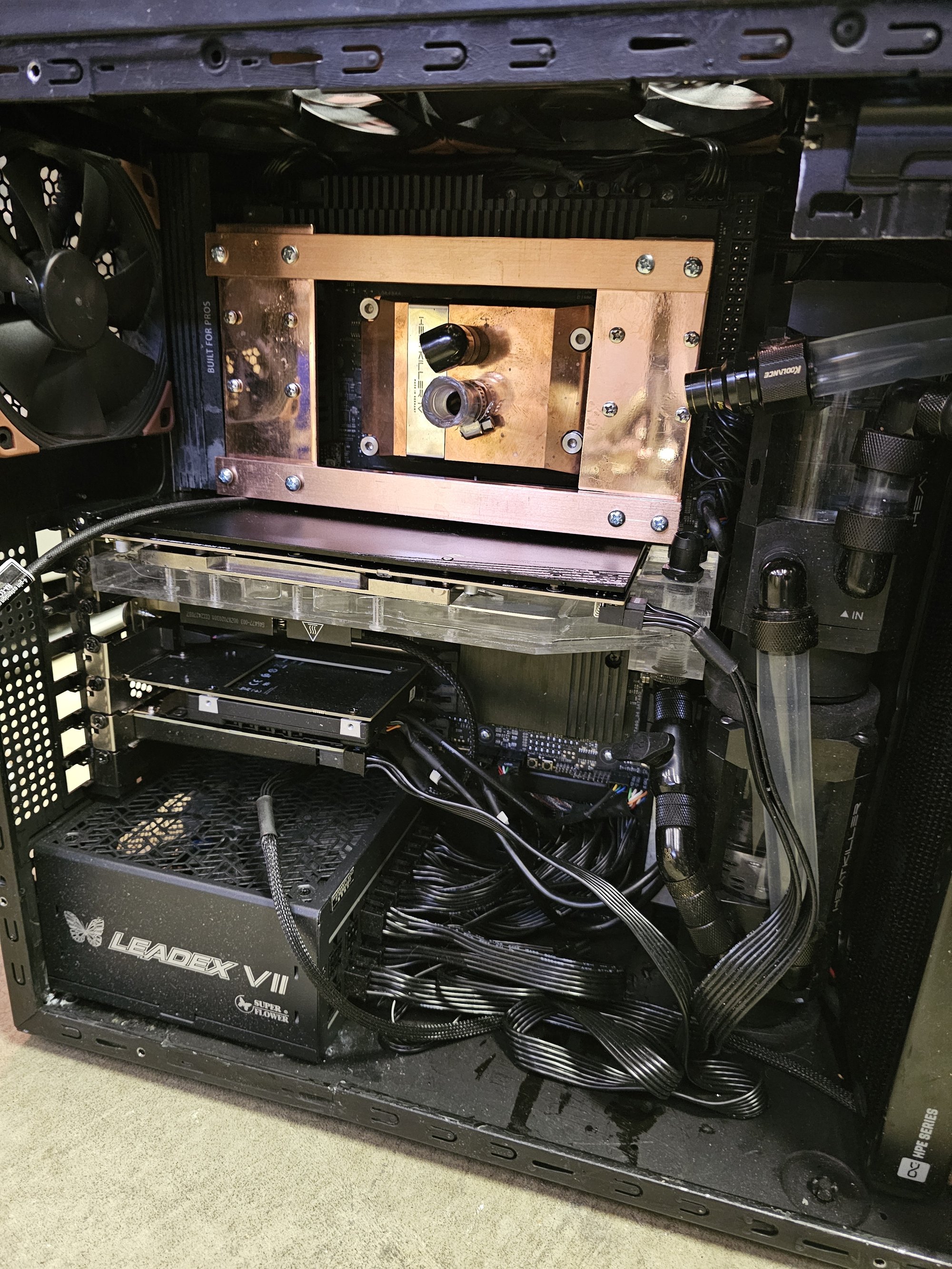
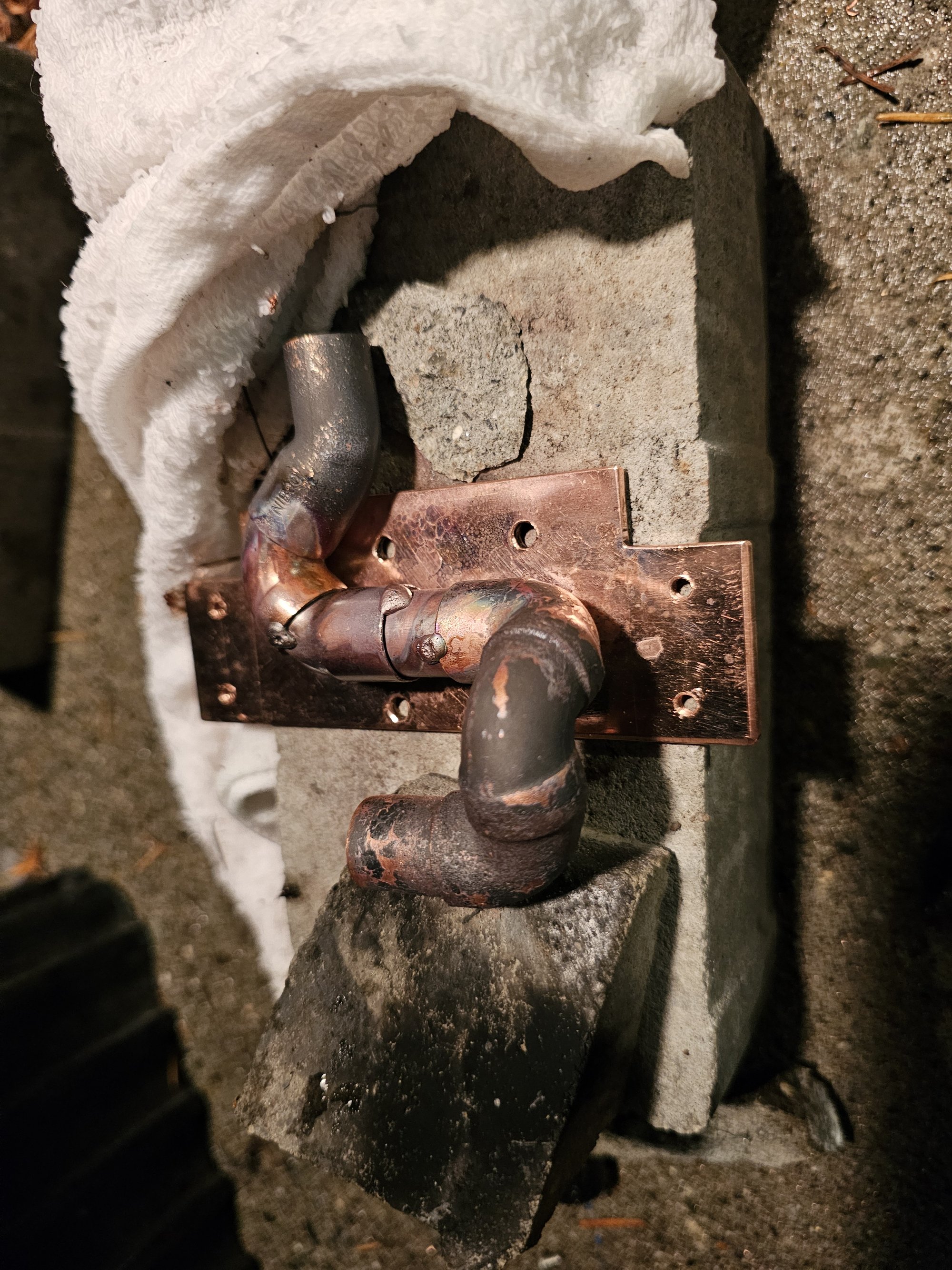
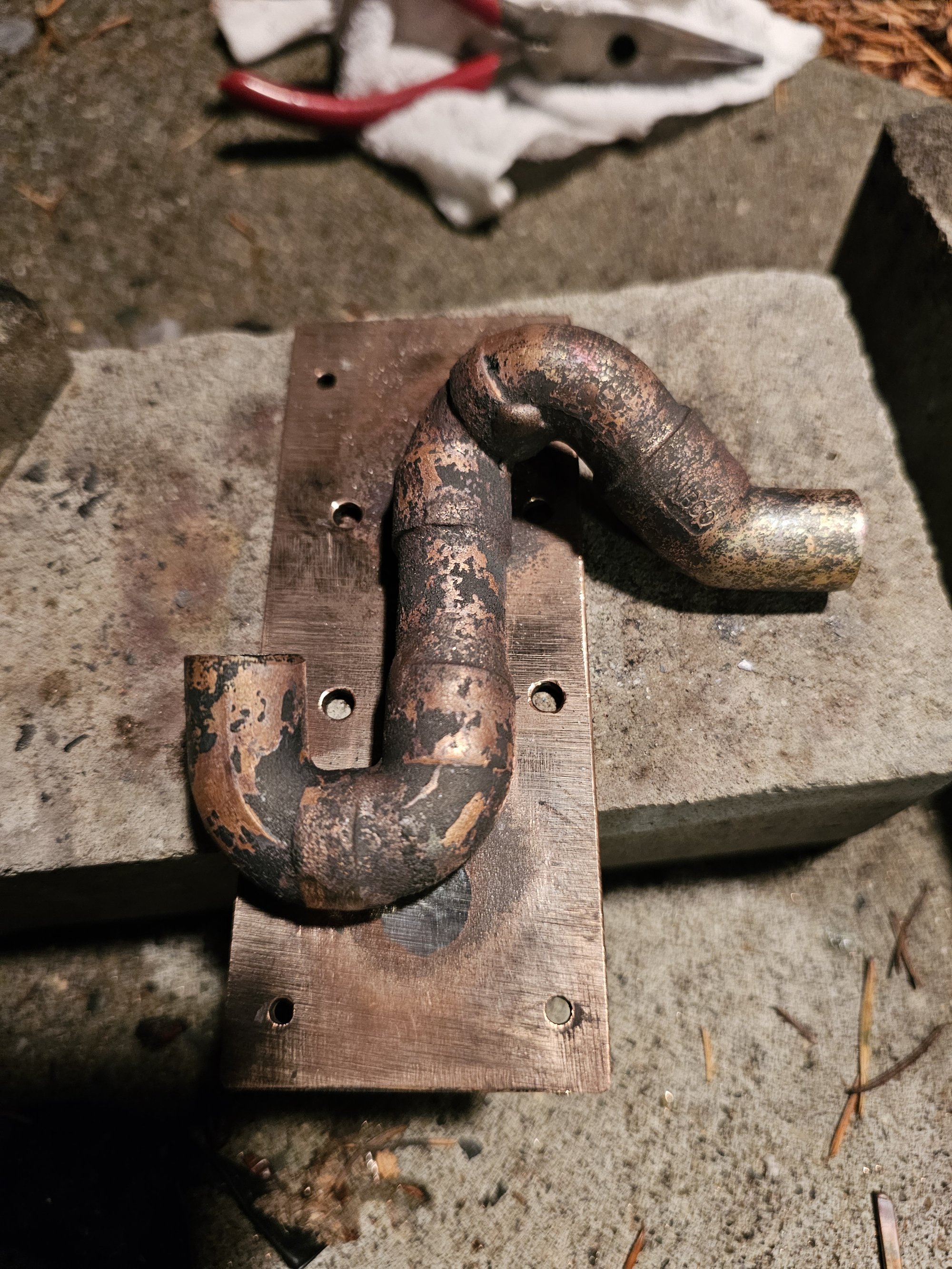
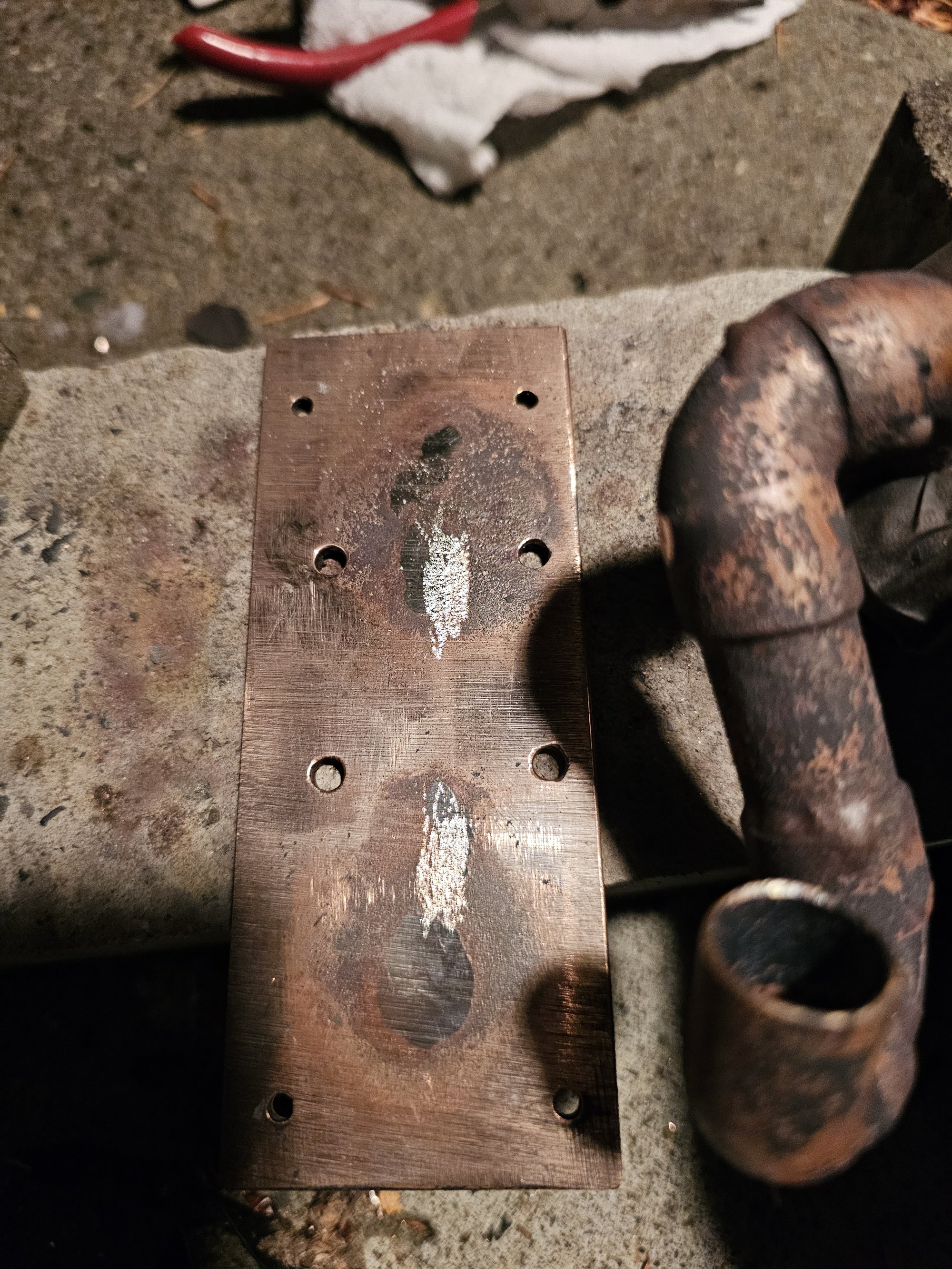
Threadripper Watercooling Attempt 1 (Old)
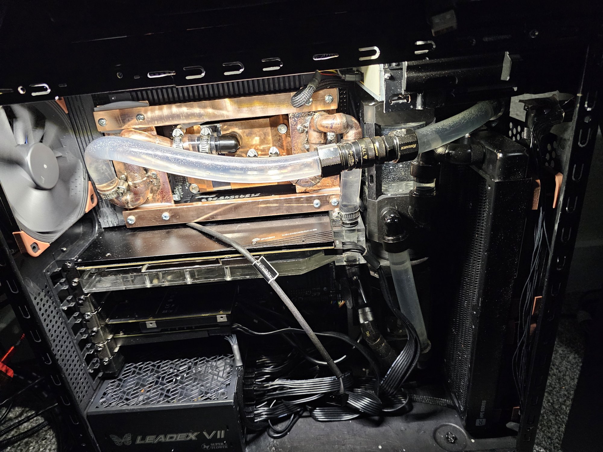
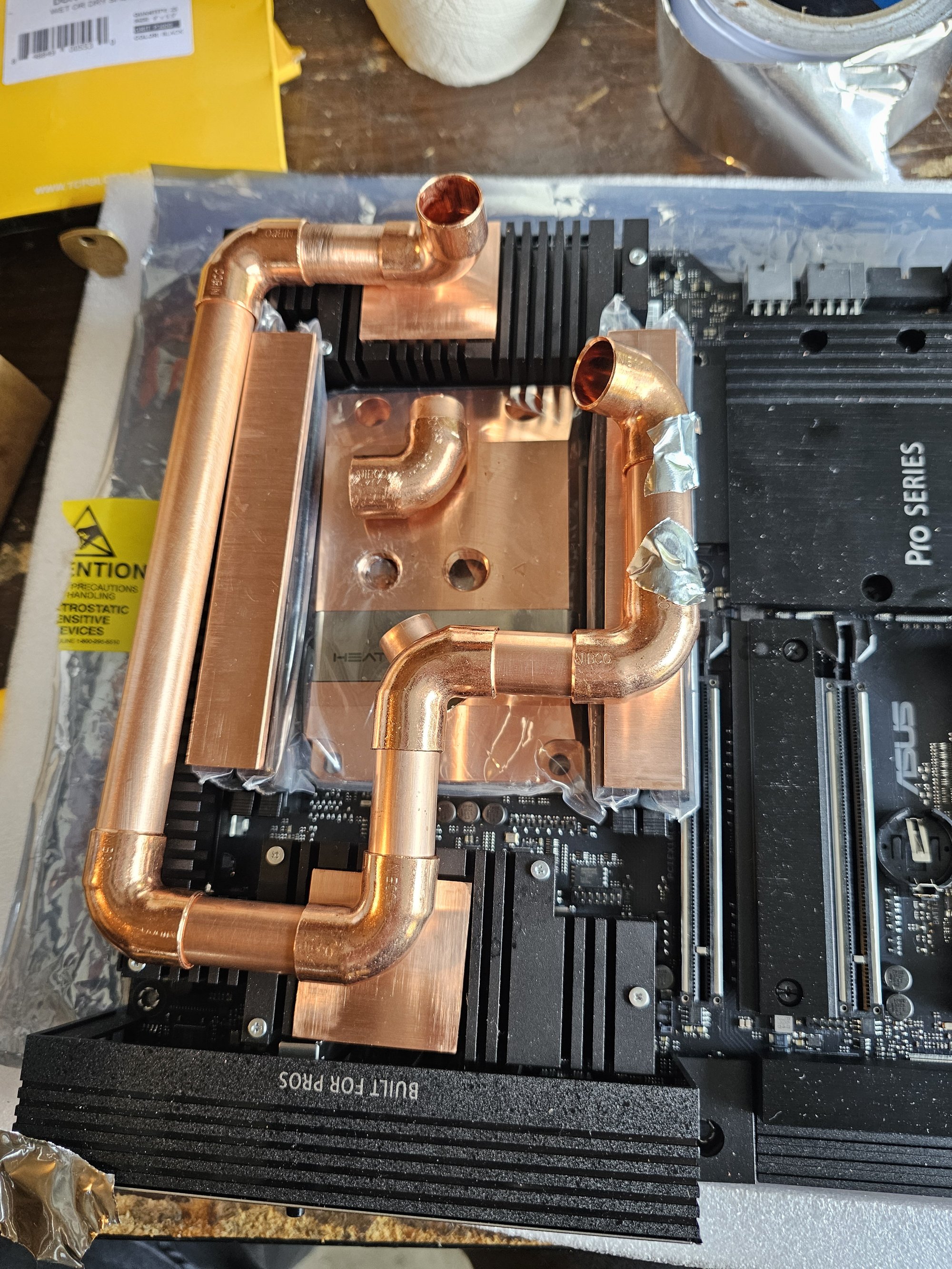
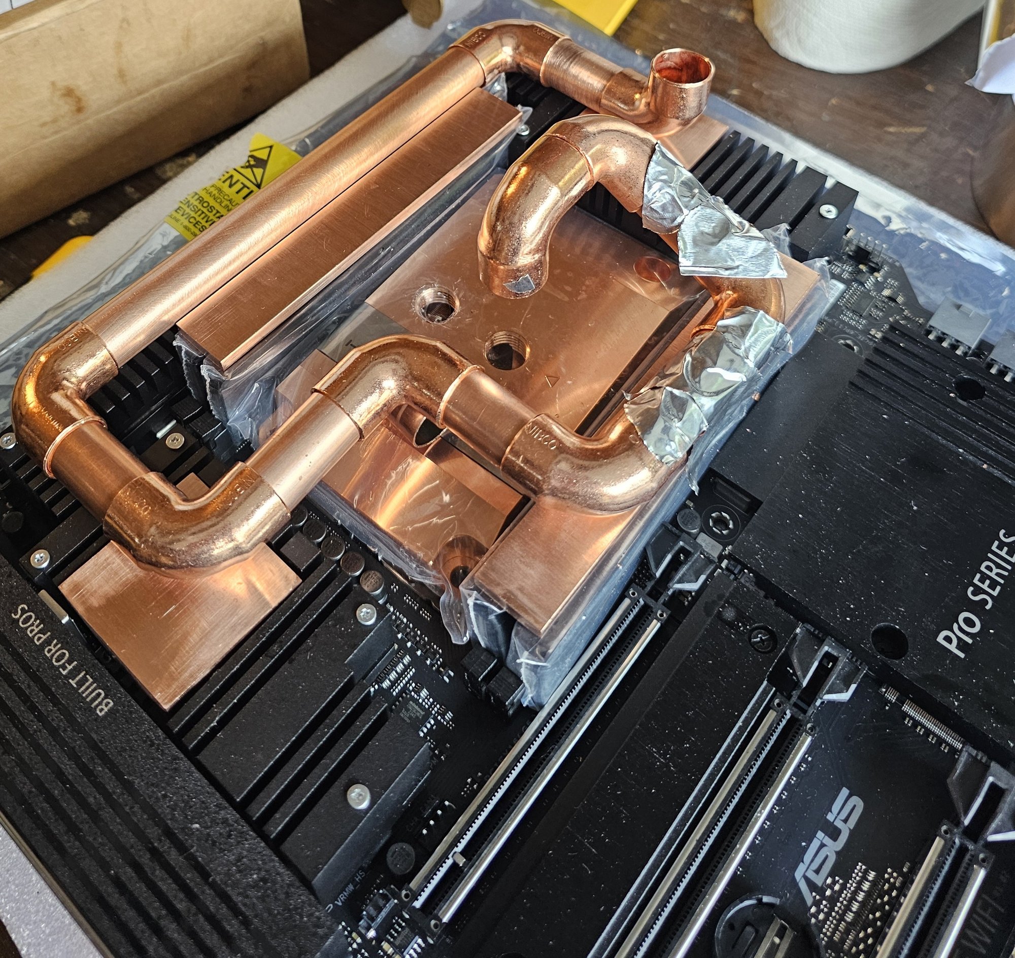
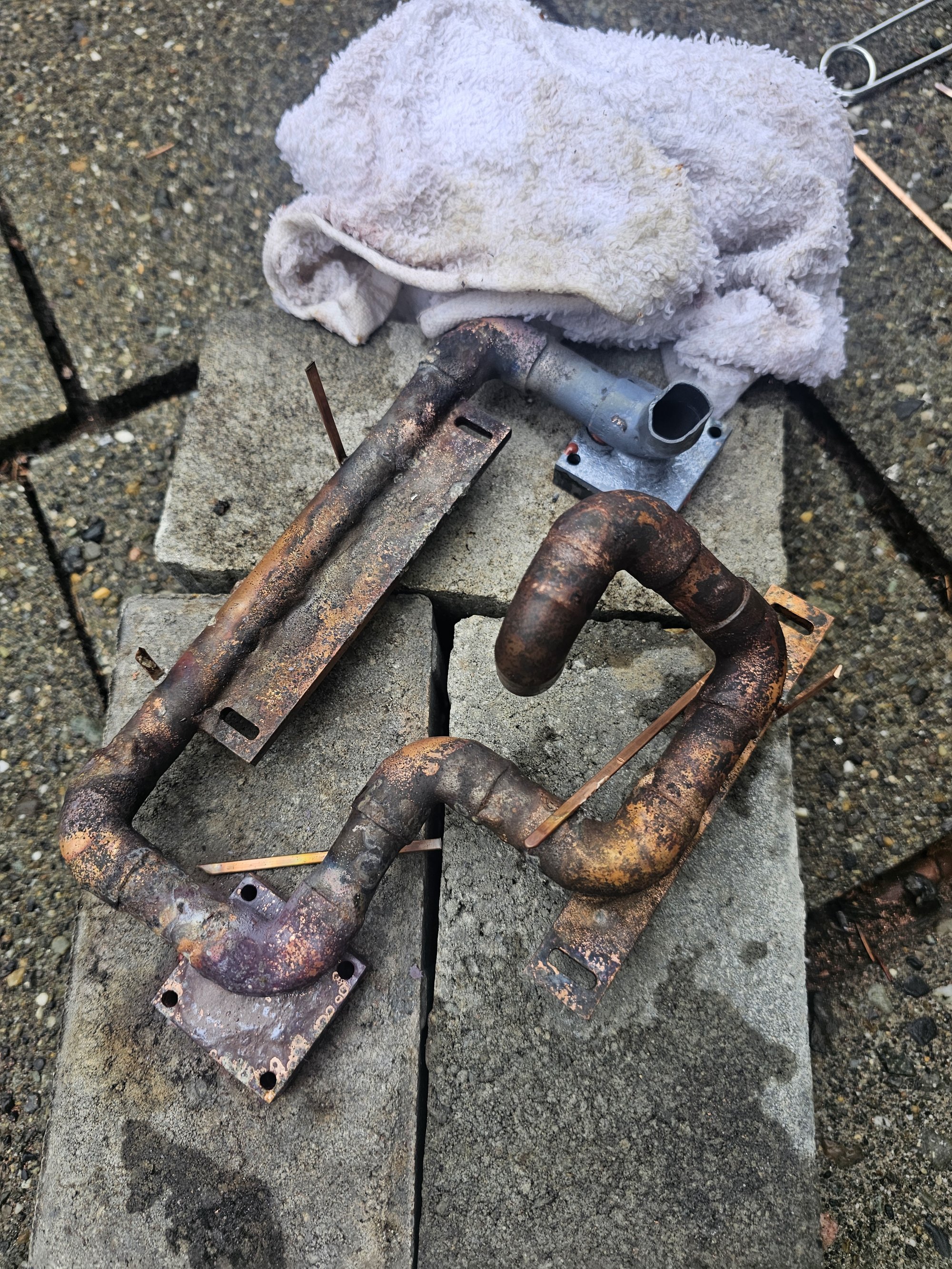
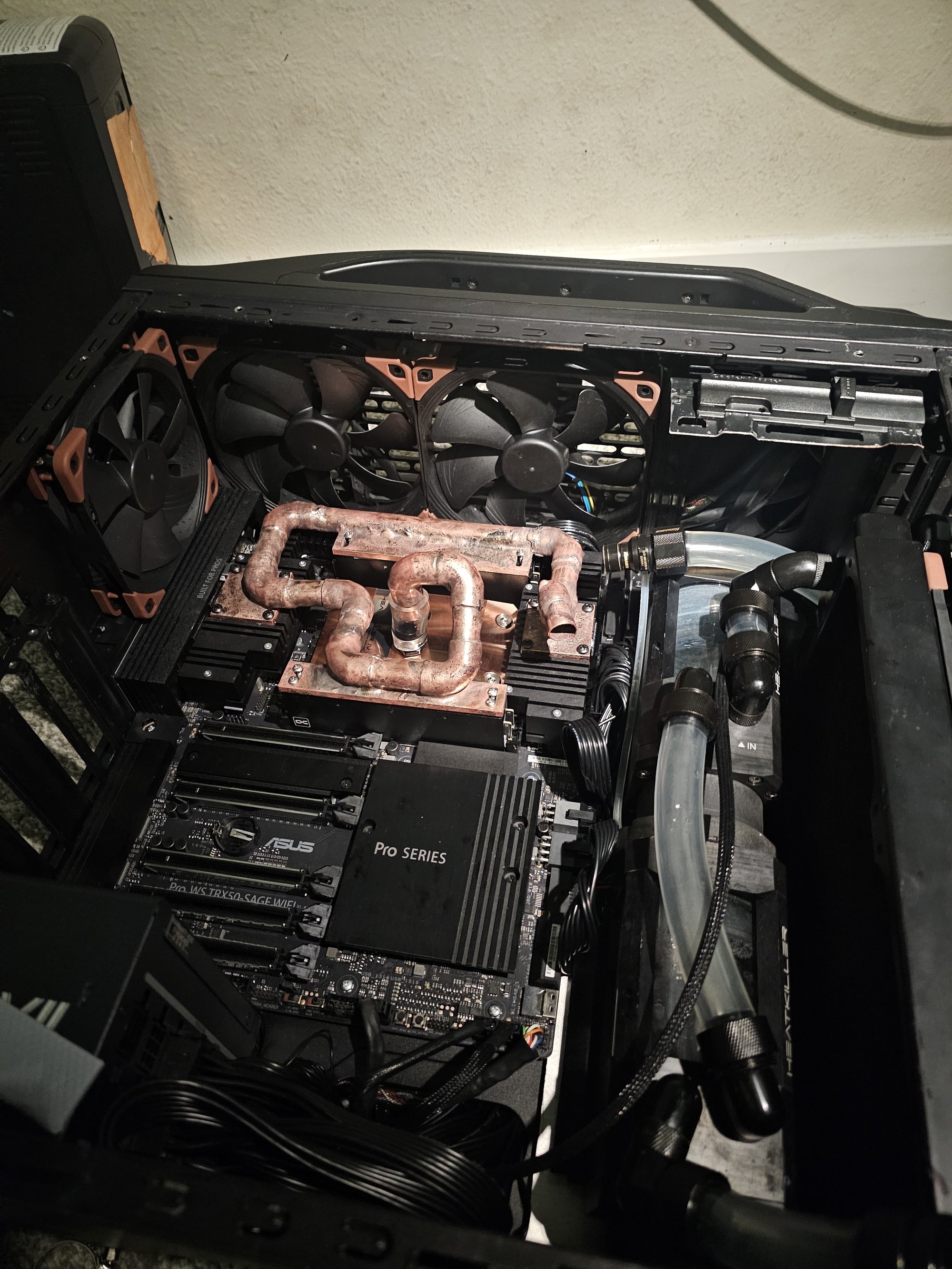
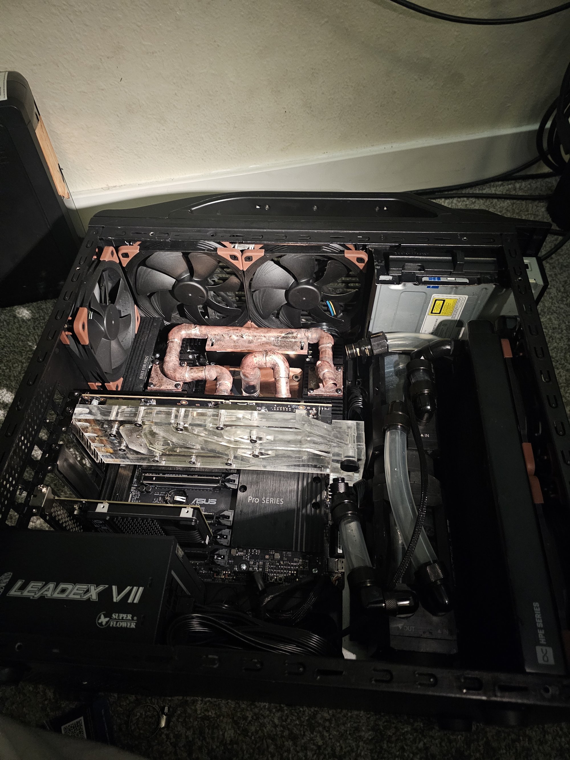
The board VRM had horrible mini active cooling fans, which are against my religion. I figured out a pretty elegant pipe noodle that hits the VRM in 2 spots (where the fans were), as well as both RAM banks. I do not have pictures in the gallery of the finished "version" of the copper noodle.
I brazed the copper with 0% silver phos-copper. I did this over soldering as silver and tin in the solder would release into the water and react with the copper and nickel on the blocks. Phos-copper also has a thermal conductivity near that of pure copper, as opposed to solder which is ~60w/mk.
I have a superior design in mind where you take the original noodle and simply dont braze it to the ram copper plates. instead, thicken these plates, put flat plates on the copper tubing to adapt the surface, and mate the two with the copper loop always running alongside the ram copper plates, never on top, then lash the two together with screws so the ram doesnt get torqued.
Shortcomings of foregoing creating a mounting jig to "save time" and doing everything freehand:
- general inaccuracies
- permanent heat warping creating inaccuracies
- reflow work creating inaccuracies
- bending out inaccuracies leading to fractures -> reflow work
- reflow work etc. creating oxidized surfaces + impurities leading to leaks and more reflow work
How I built the noodle freehand:
- Assemble loop mounted
- Tack all joints with permatex 84145 (more resistant than superglue)
- Apply soaked cloth to keep unworked areas cool to not melt adhesive
- Braze or glue brazing rod or similar to act as scaffolding if needed
Watercooling Overhaul
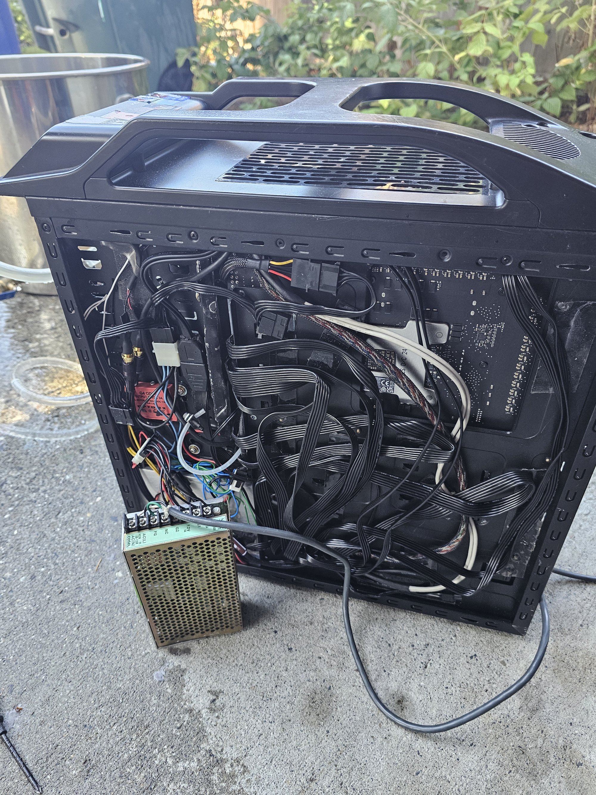
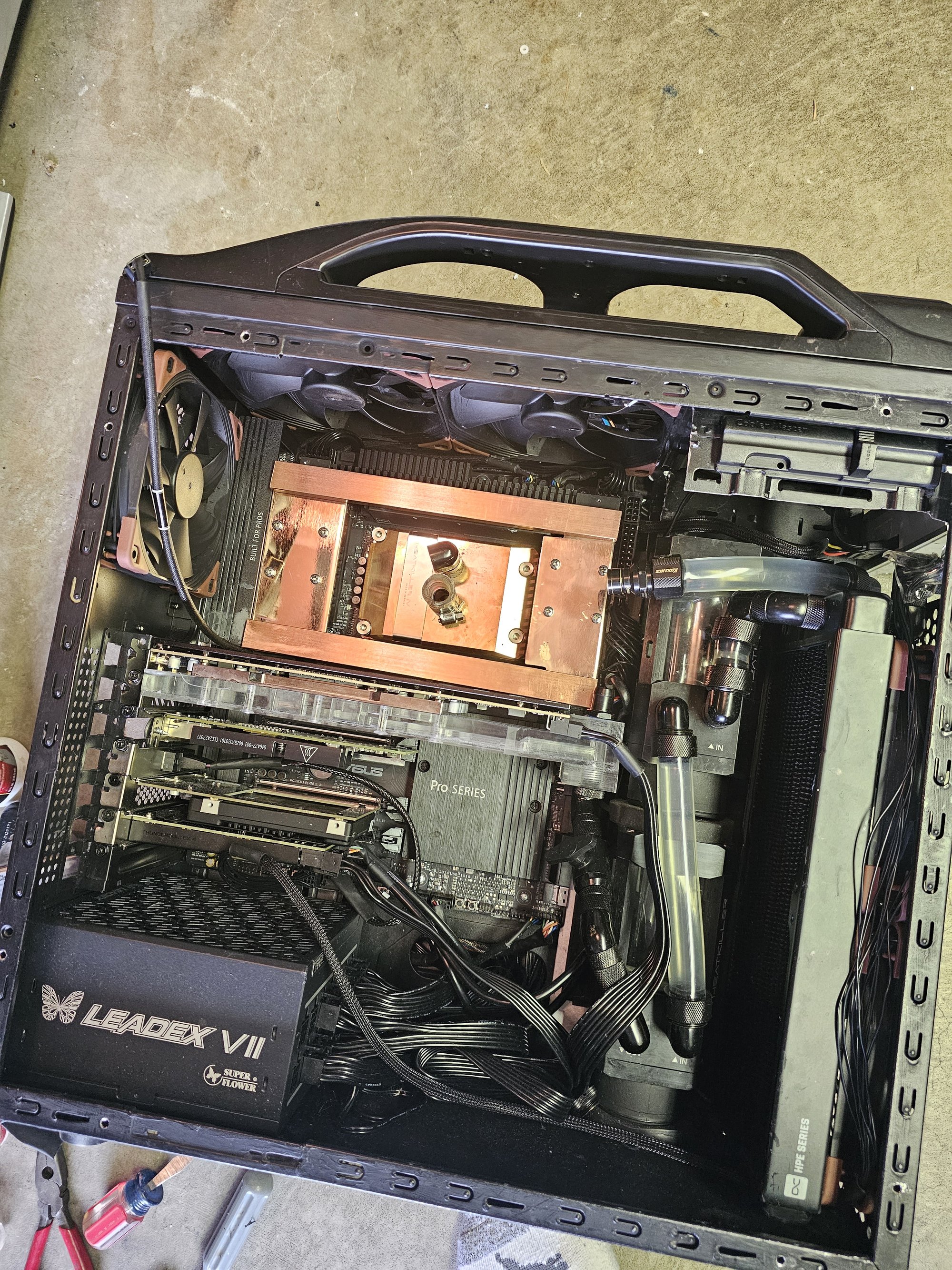
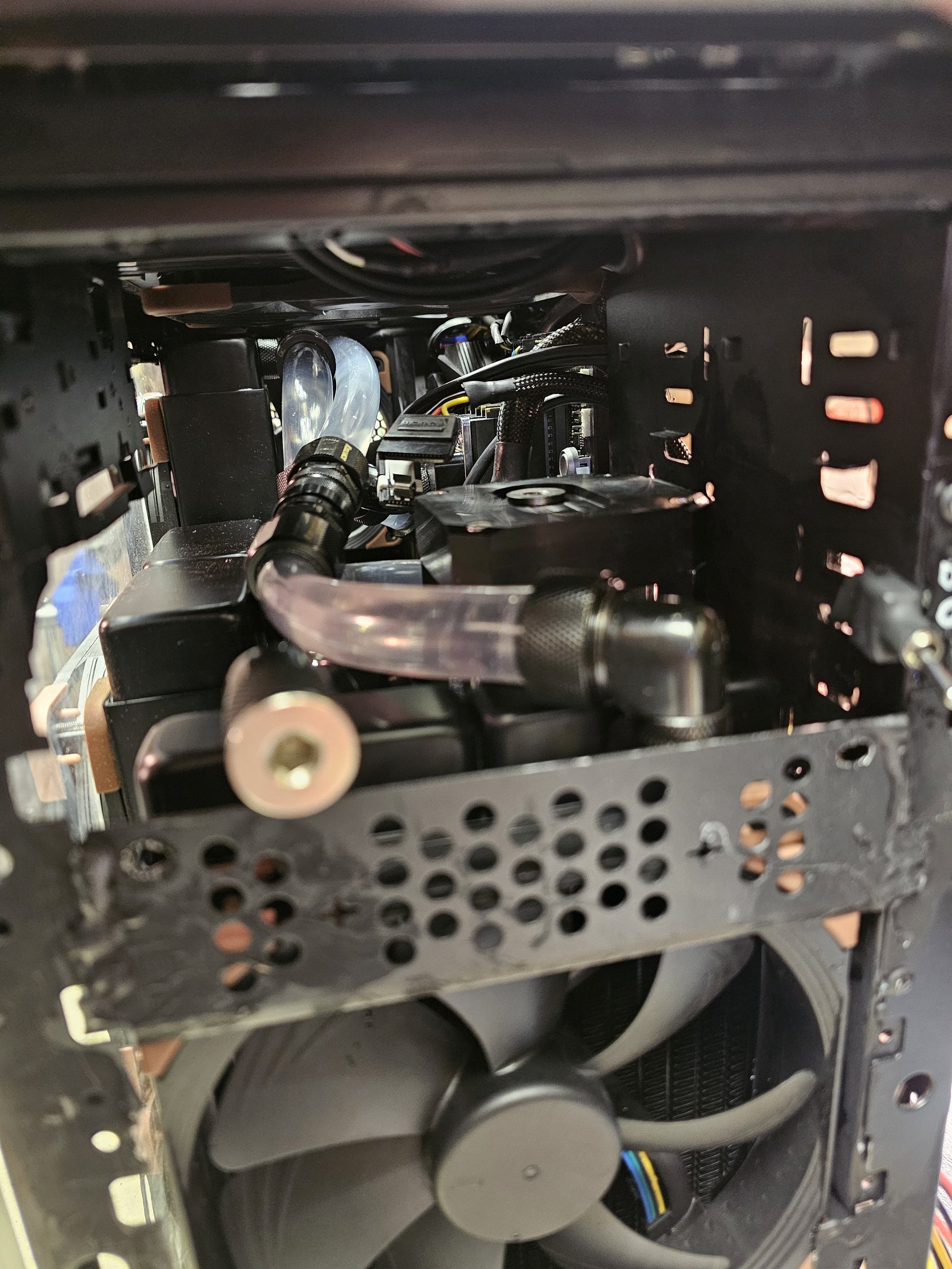
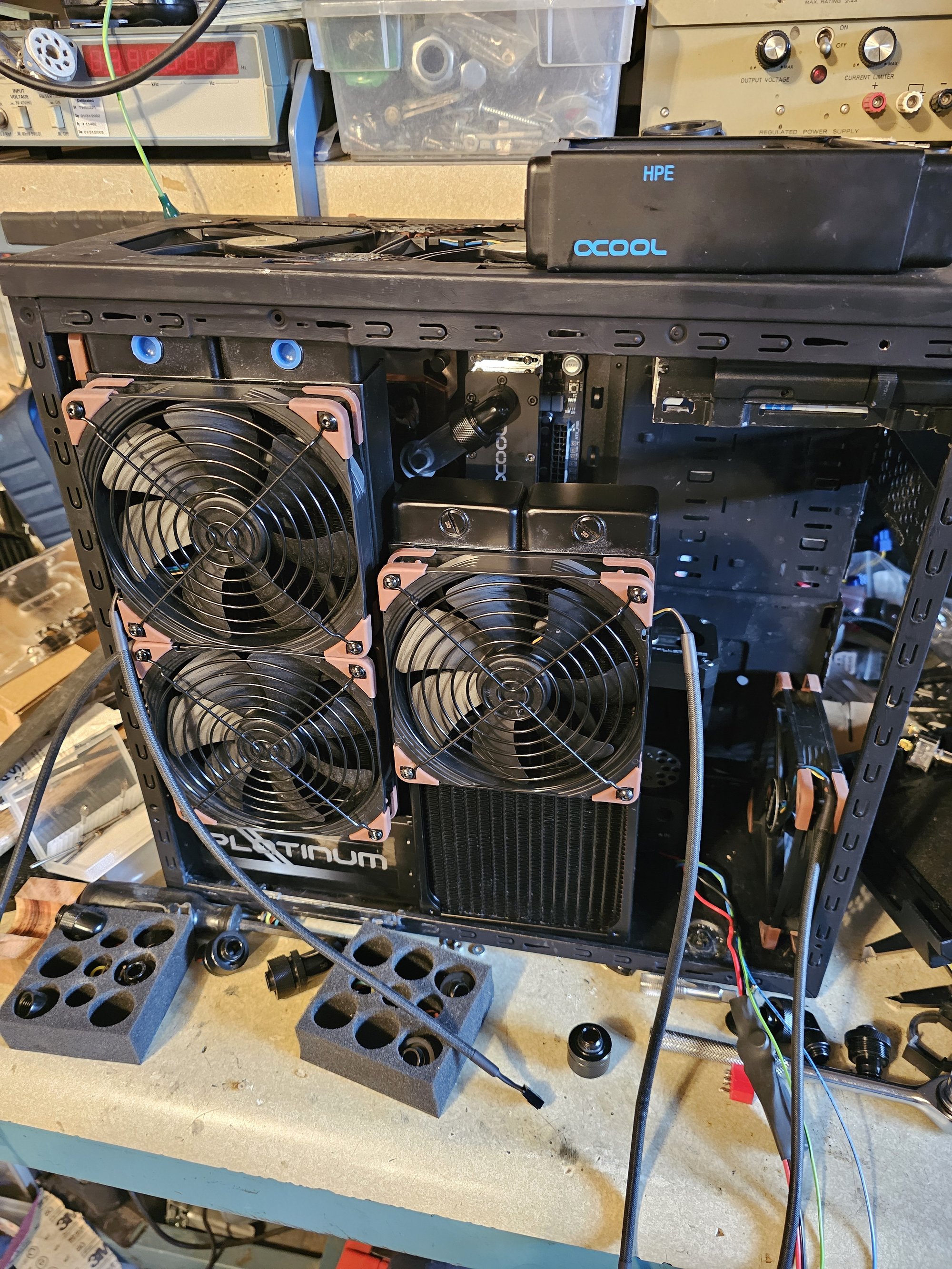
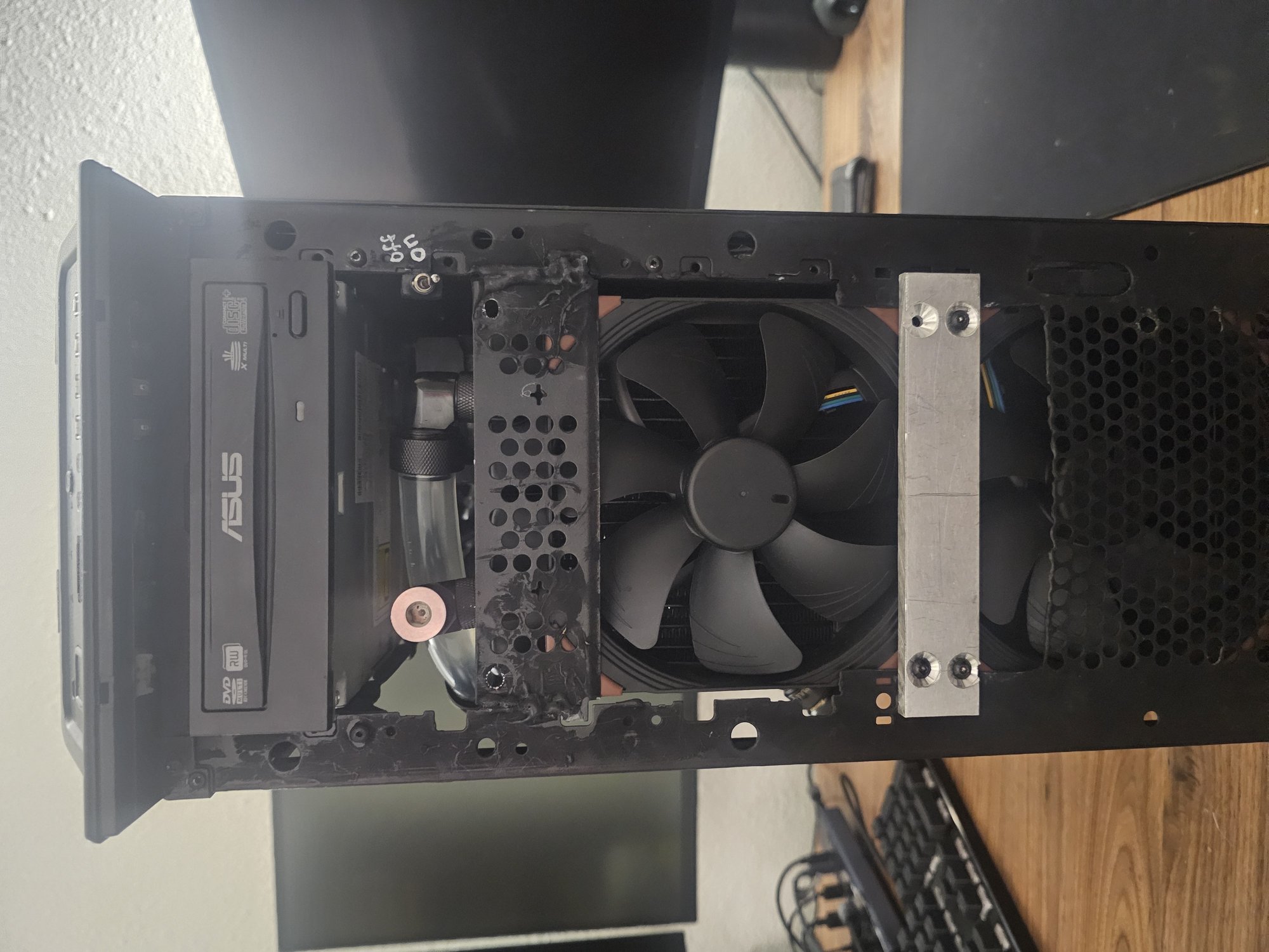
I've had the same cooler master storm scout since the beginning and have modified (gutted) it over the years to accomodate new hardware. Here's a showcase of what it looks like at the moment.
Special features include:
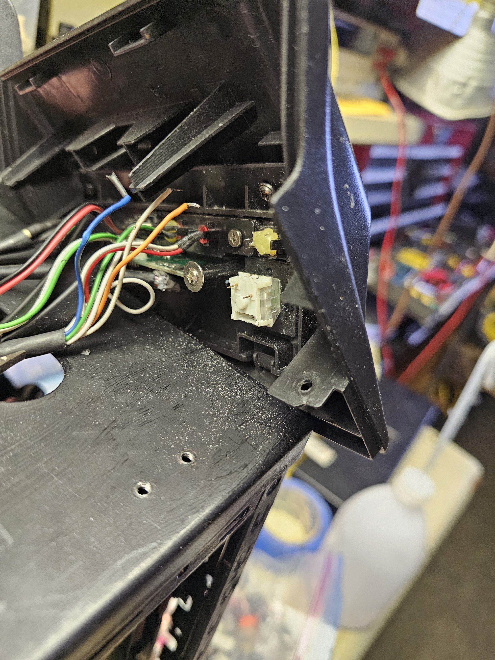
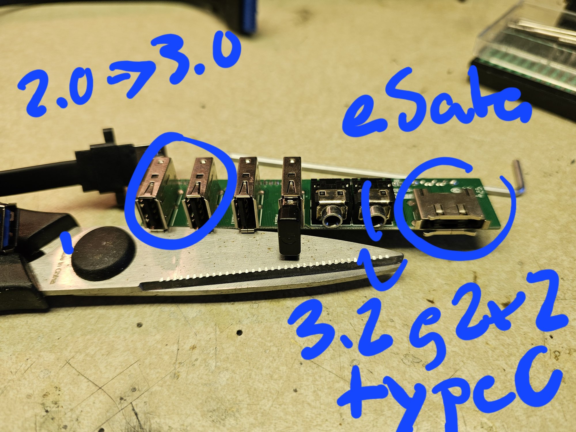
- Upgraded front panel I/O.
- swapped 2x usb 2.0 ports for 3.0 ports
- changed the eSATA port to a USB 3.2 2x2 type C
- replaced the power button with a kailh box jade
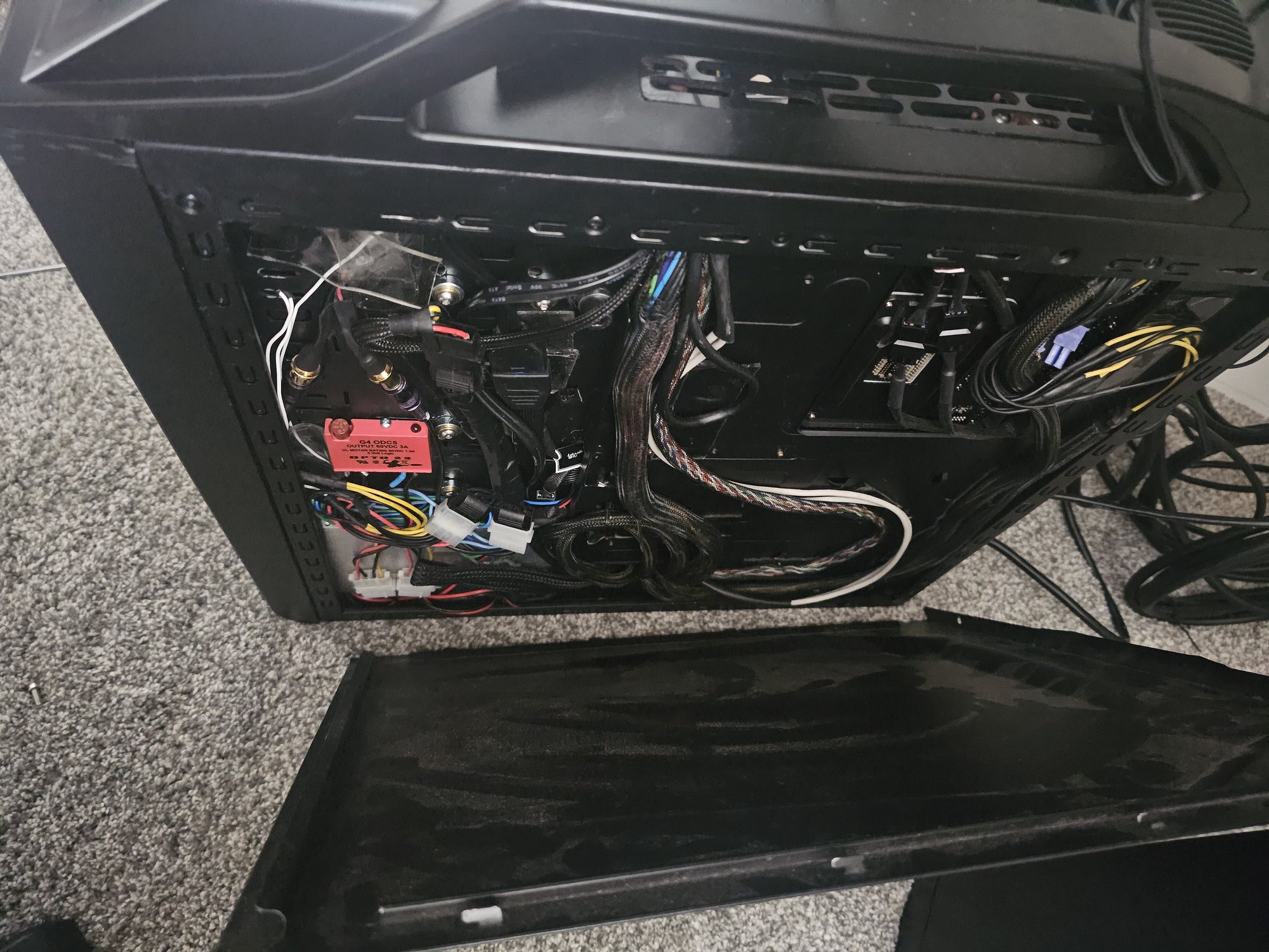
- rewired the red led button to a relay for 12v LEDs
- Pump(s) on/off switch
- Drain port (tilt case to use)
- Quick disconnect side panel
- Connector pairs are wired out of phase, so you can "short" the two ends together to run the PC without the side panel
Top Panel & Airflow
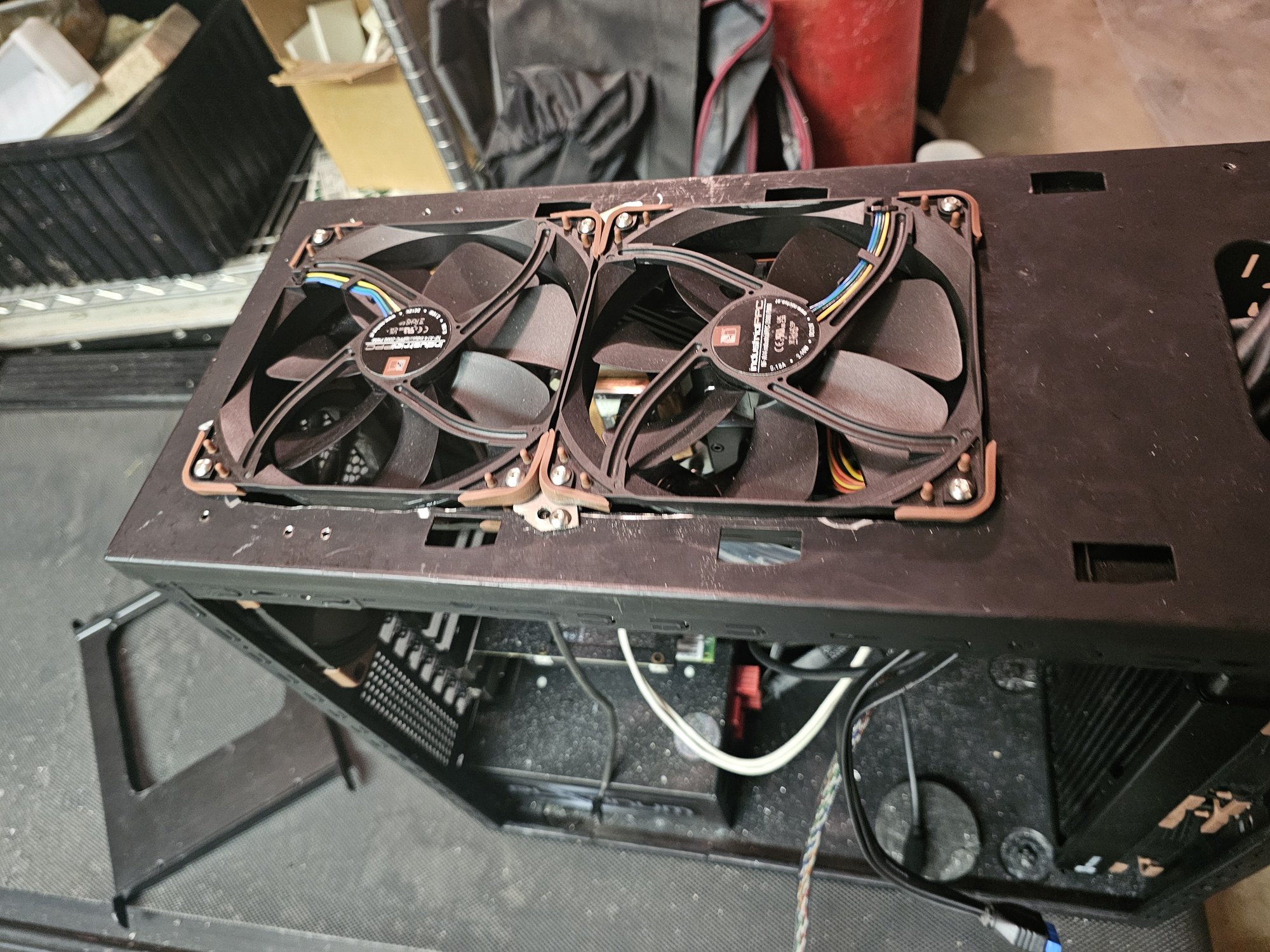
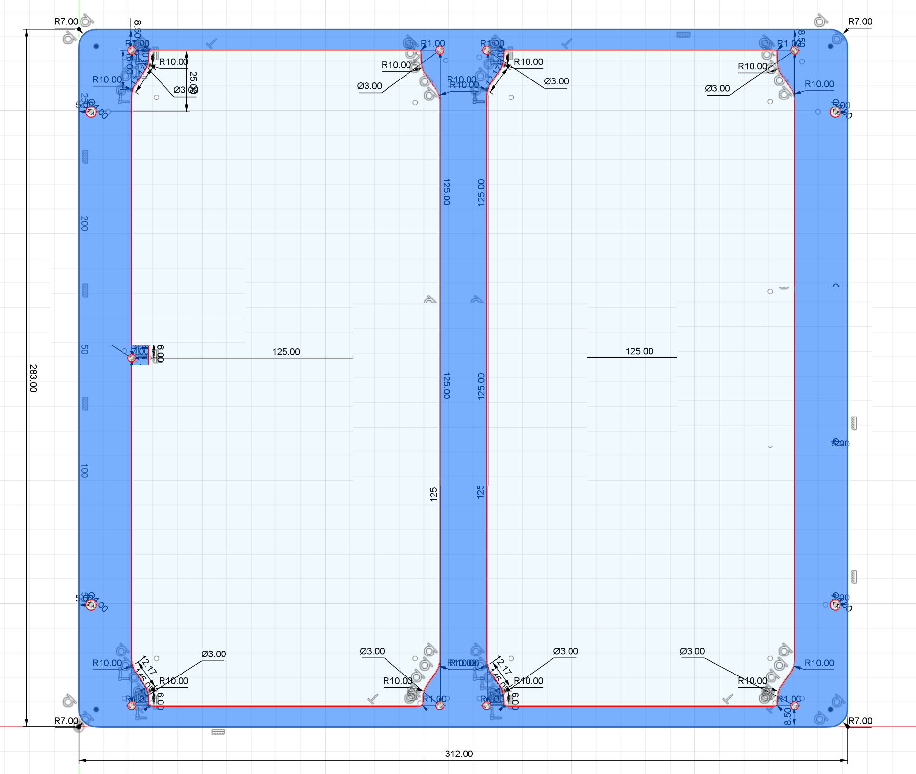
The top vent was CNC'd out of the inner panel (the top shell is two separate panels). A new grill was CNC'd from Kydex. The outer rear section was hollowed out to support airflow across the full 140mm fan surface area. The internal chassis (essentially a rectangle) was modified with a Dremel to accommodate 2×140mm fans in place of the original 1×120mm mount.
Side Panel Radiator Mounting
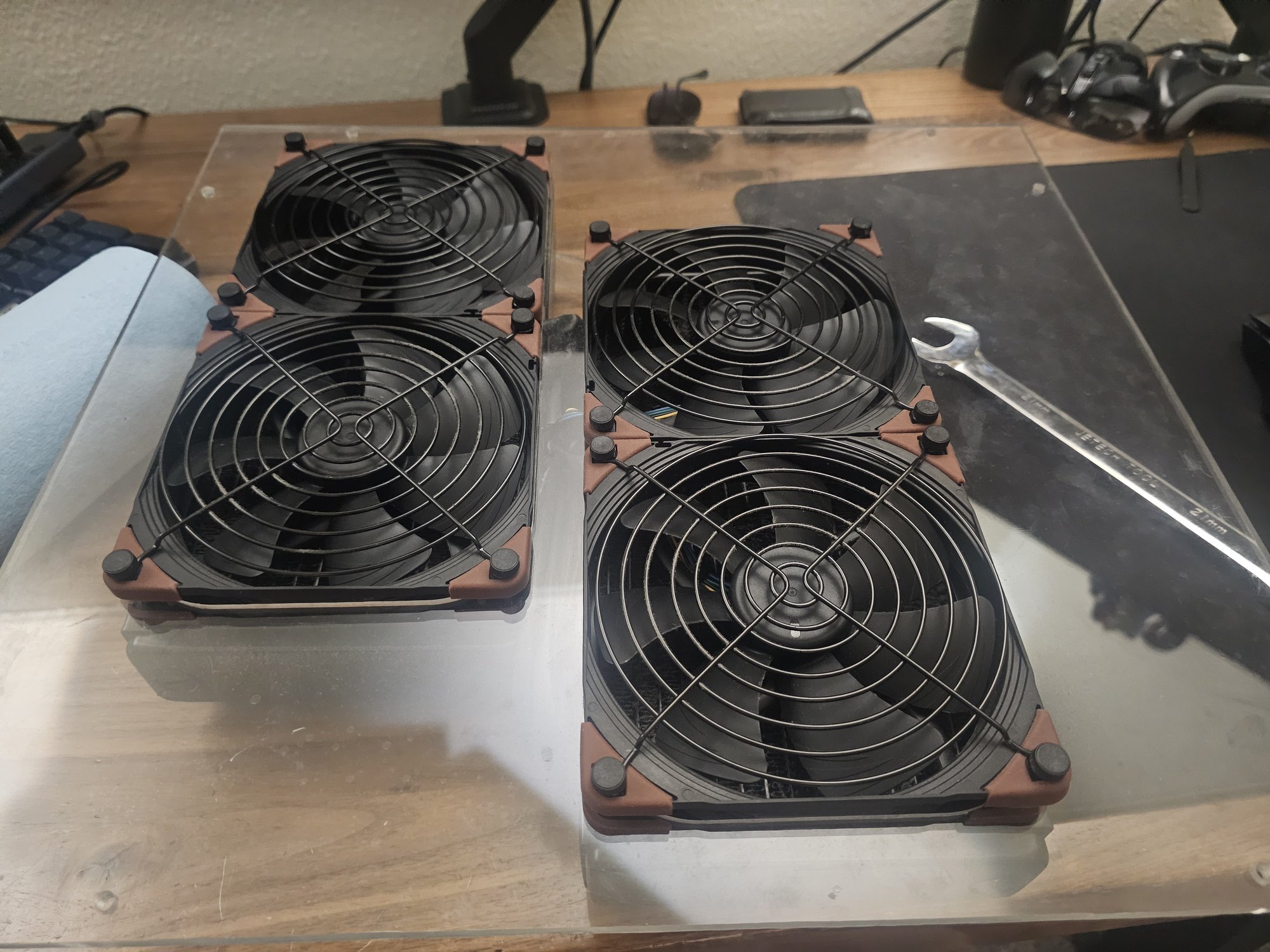
Each dual radiator mount uses a single hole. The fans slip in so the plexiglass rests between each side of the fan body. Once mounted to the radiator, their vertical position is fixed—they can't back out. The mounting holes sit on fins protruding from the circular fan shell (visible in the gallery above).
This design allows selectable radiator/fan depth within the side panel. I floored them to the outside, but depth can be adjusted using nuts along the fully-threaded mounting screws.
Reservoir Modifications
Both Heatkiller MP reservoirs were shortened by 25mm (100mm → 75mm). The process is straightforward: drill and tap deeper into one end of each aluminum strut, cut/grind it down (drill + tap screw first!), then trim the borosilicate glass to match. I learned the hard way you have to cut glass wet. The thick silicone O-rings at each end make all this forgiving.
Vibration Dampening
The pump/reservoir assemblies are dampened at three points with 30 durometer Sorbothane:
- Pumps — Sorbothane pucks underneath, compressing against the case floor
- Reservoir mounts — Sorbothane layer between each mount point and the back panel
- Back panel — Attached to the chassis at only two edges; the free corner is wedged away using sorbothane and a strut plate
To improve shock isolation, the chassis plate holes were dramatically oversized. Bushings and shoulder washers give the mounting screws oversized heads, allowing the reservoirs to float—stress only pulls them into the sorbothane.
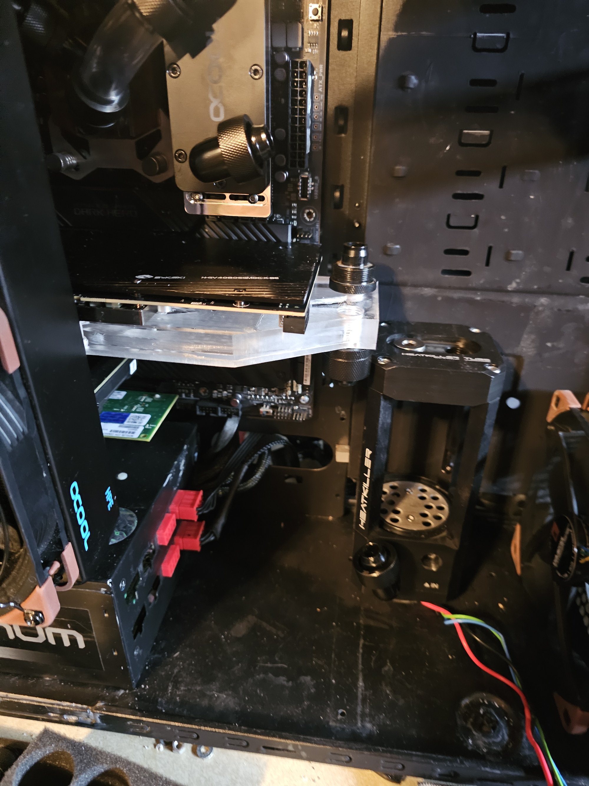
Lower Reservoir Bleed Solution
The lower reservoir is plumbed as an air pocket due to clearance constraints preventing a top fitting. This eliminates waterfall noise regardless of coolant level, but requires opening the case to bleed air during filling.
Solution: Drilled out a fitting, routed 1–2mm silicone tubing through it, and sealed with silicone. The tube runs to a custom valve machined from stainless bar stock and M8 screws.
Misc
- Cable management: Double-sided silicone tape on the backside creates a tacking surface—cables stay exactly where pushed.
- LED power switch: Added RCA connectors (only decent connectors on hand).
GPU
Background
I have a Windforce 4080 Super, which went through one or two PCB revisions post-release and isn't a common die/aftermarket make—finding any compatible block at all was lucky.
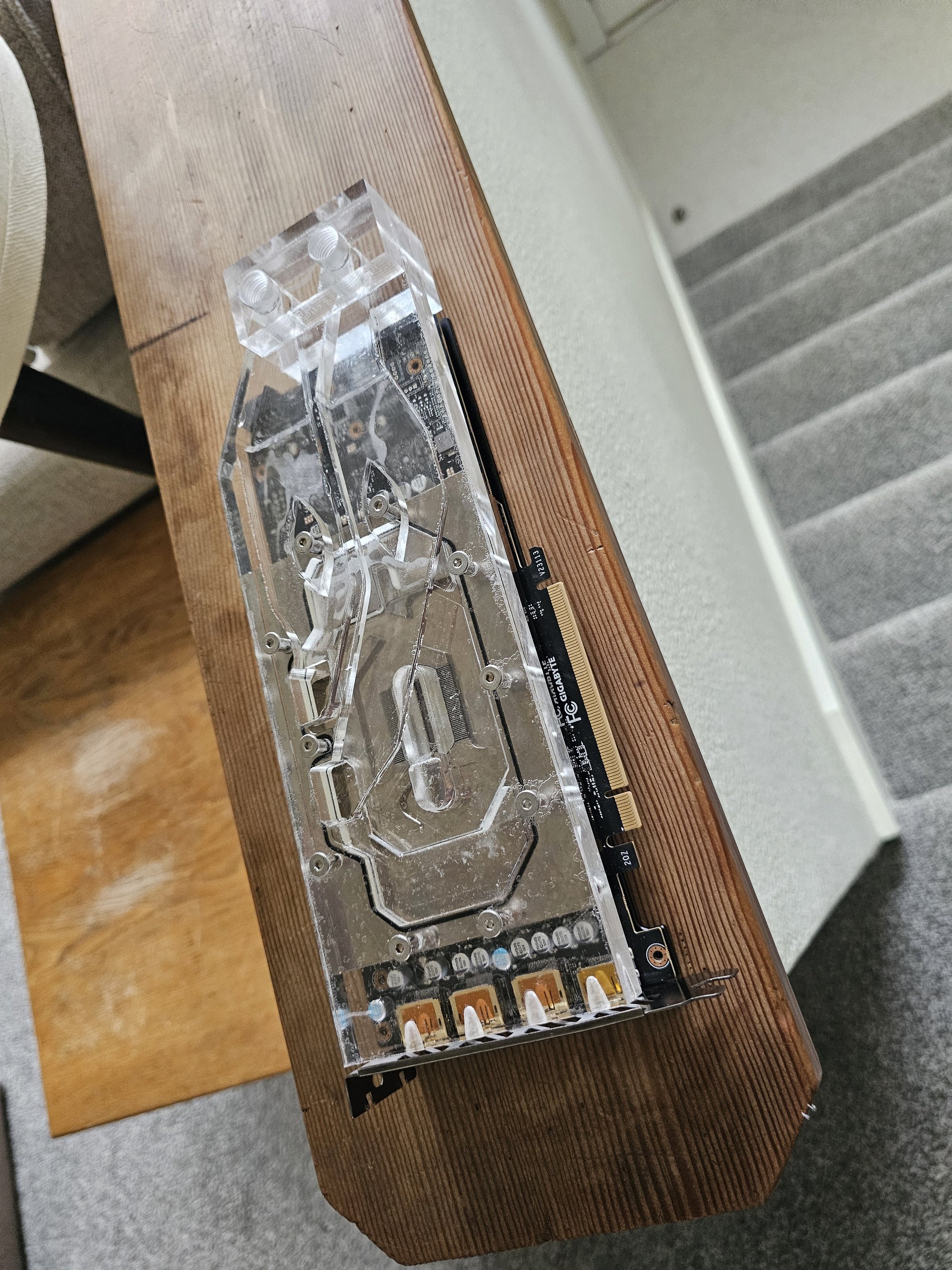
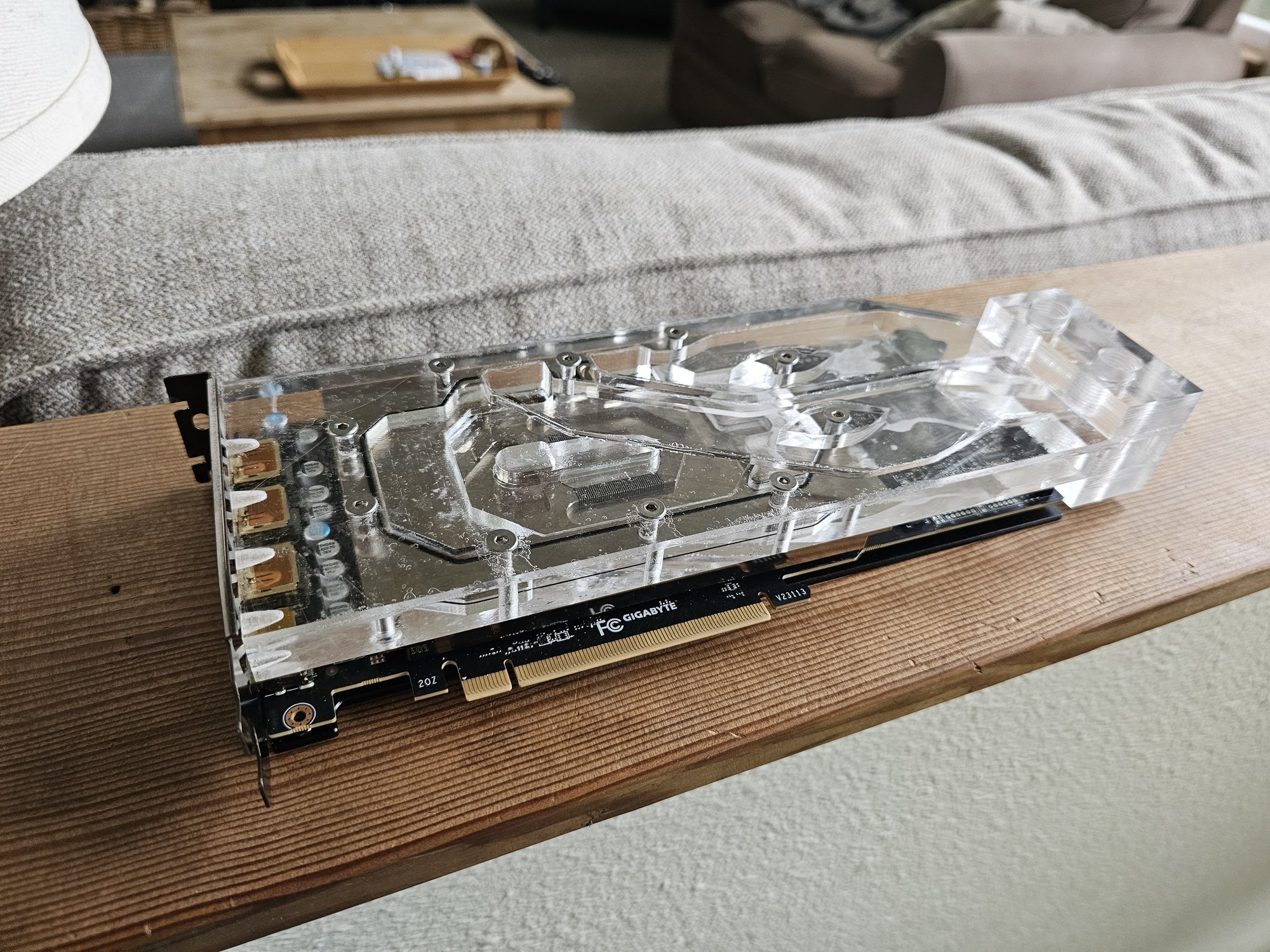
The stock block's side-mounted ports needed to be rerouted to the rear to fit behind the radiators.
Fabrication
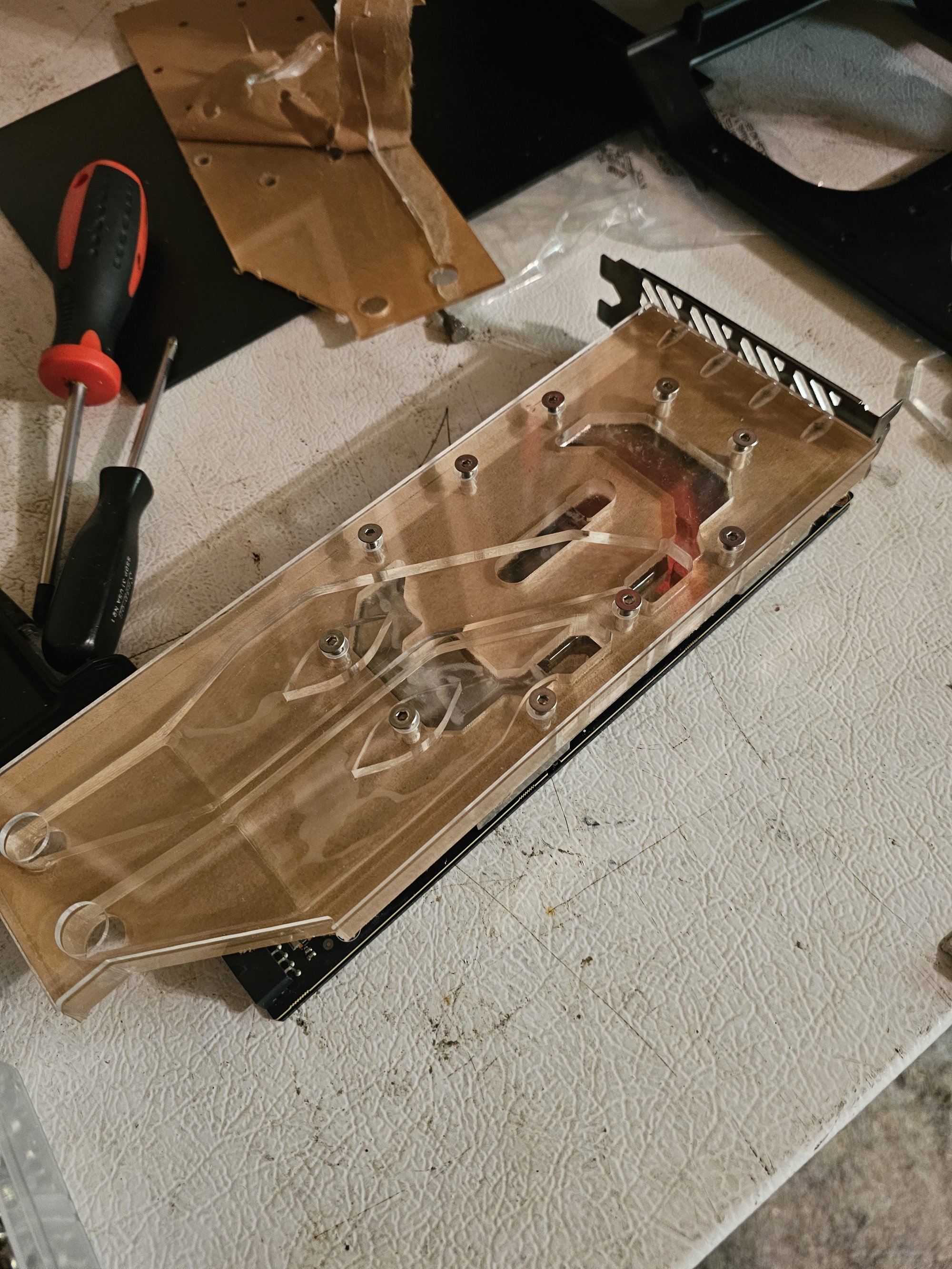
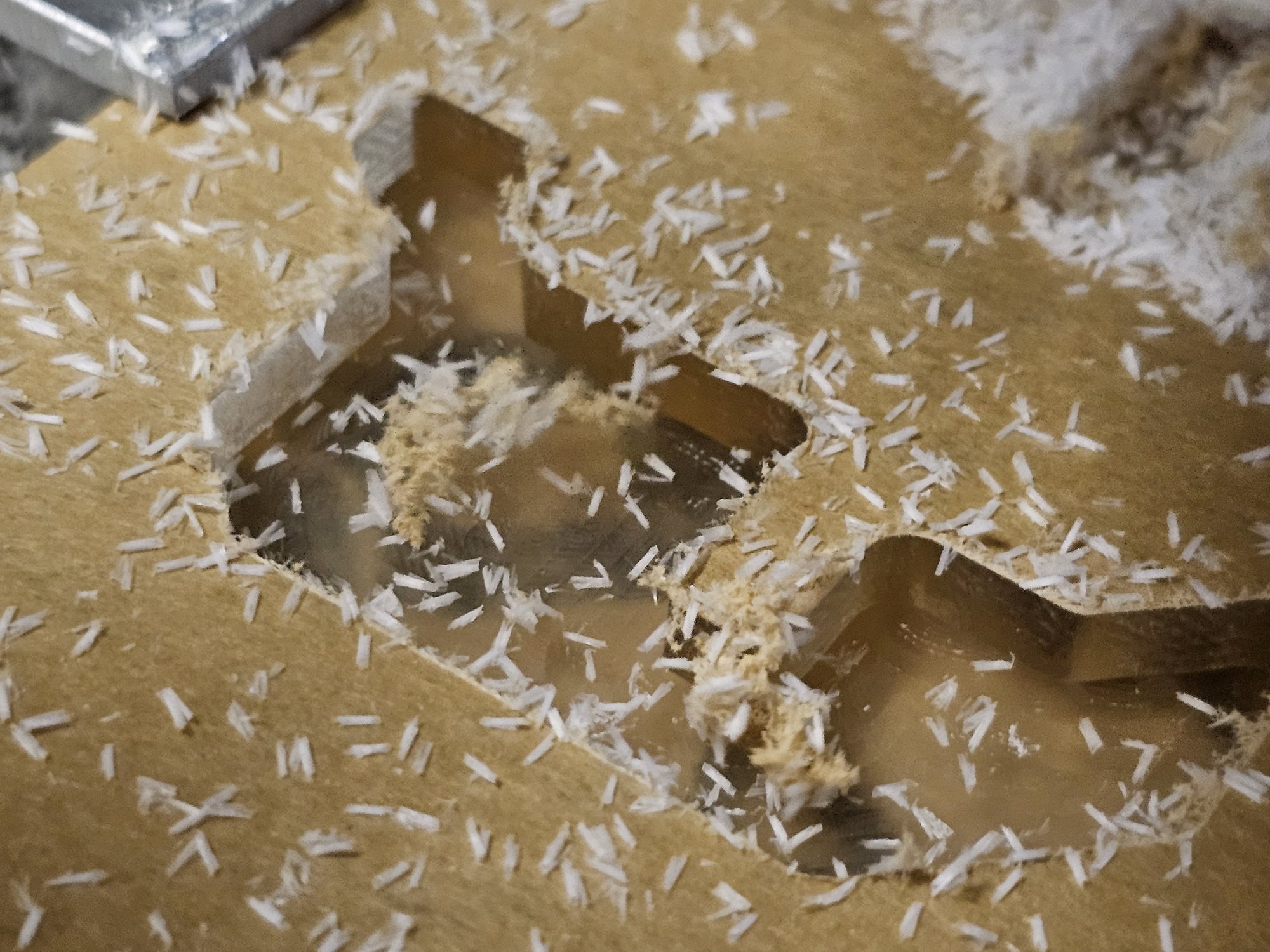
I cloned the existing block's geometry with calipers and added a new layer of shallow, wide channels. A top cover piece was welded on using IPS Weld 16 to seal them. Two thick port blocks were then welded on to complete the assembly.
Note: Use a plastic cement with gap filler (liquid acrylic or similar polymer). Solvents (welder) alone will leave cracks that leak. Learned this the hard way.
Conventional GPU blocks use the metal cold plate as the channel cover—not an option here since the reroute required a fully acrylic sealed layer.
Tapping G1/4 threads in acrylic sucks.
Case Overhaul Gallery
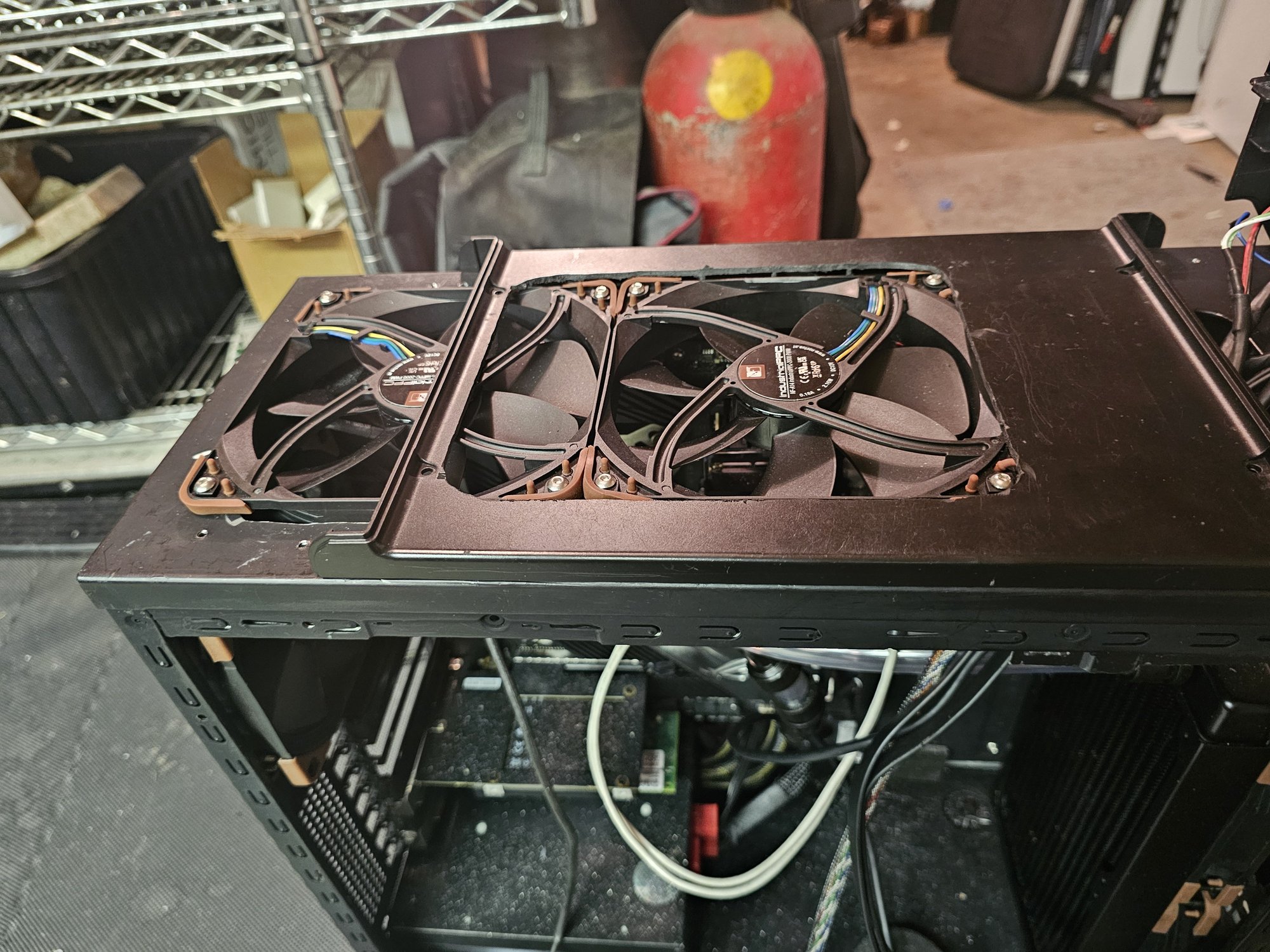
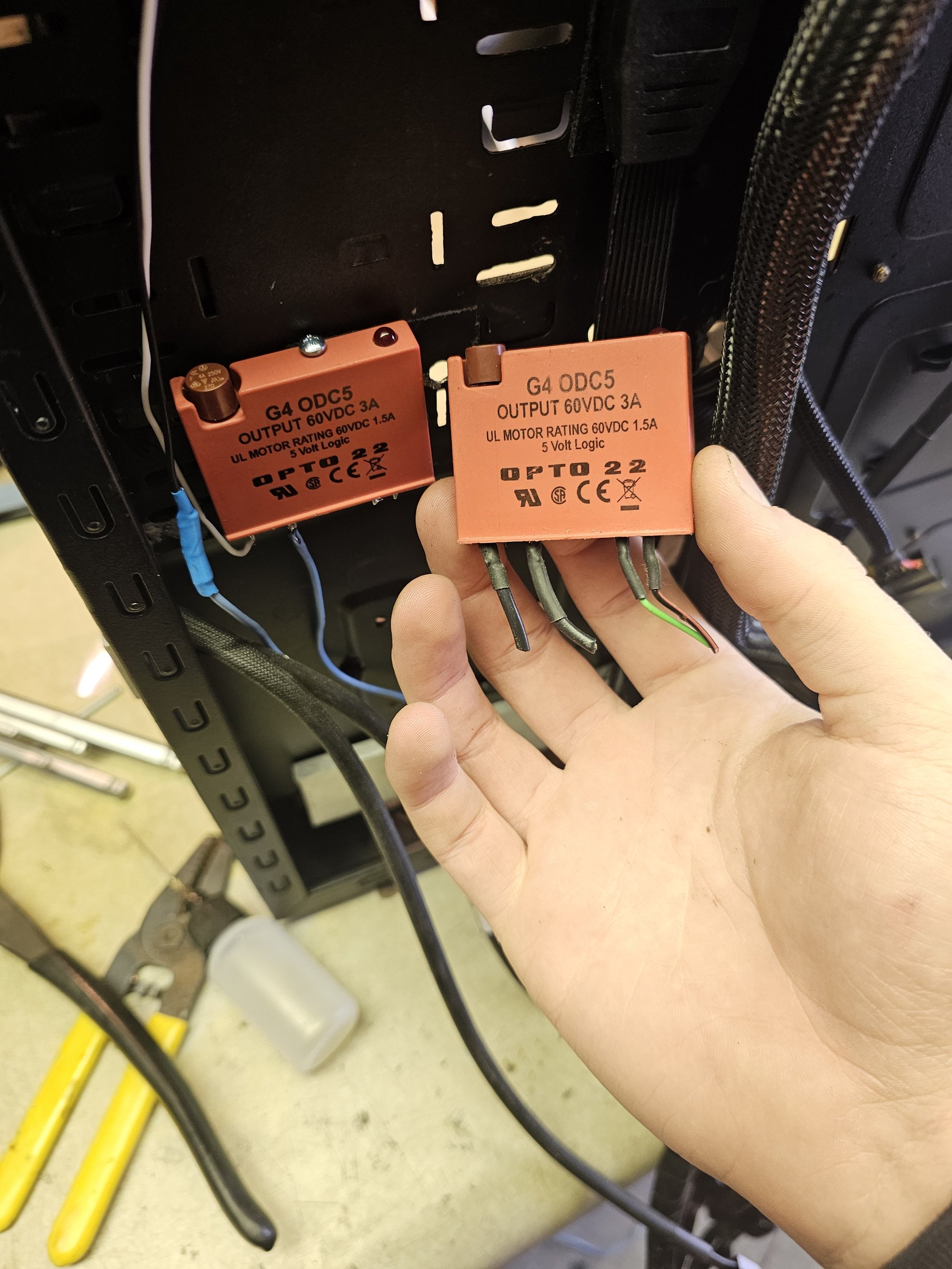
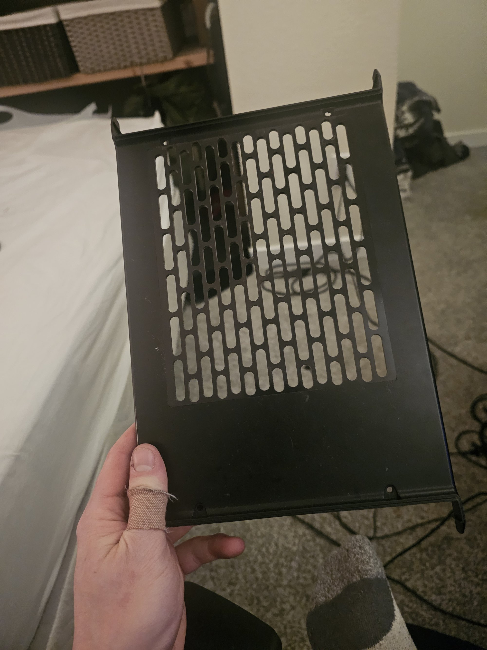
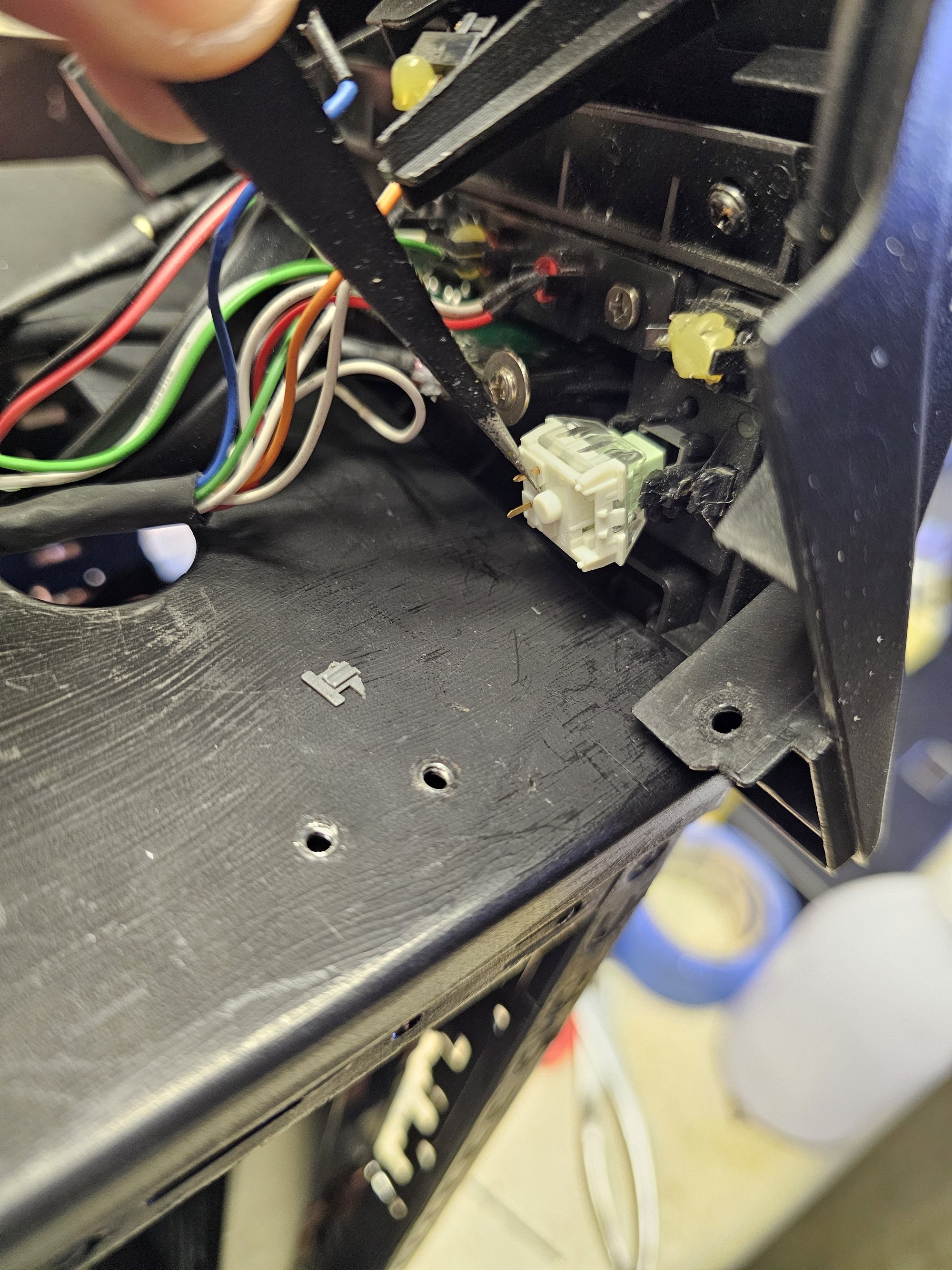
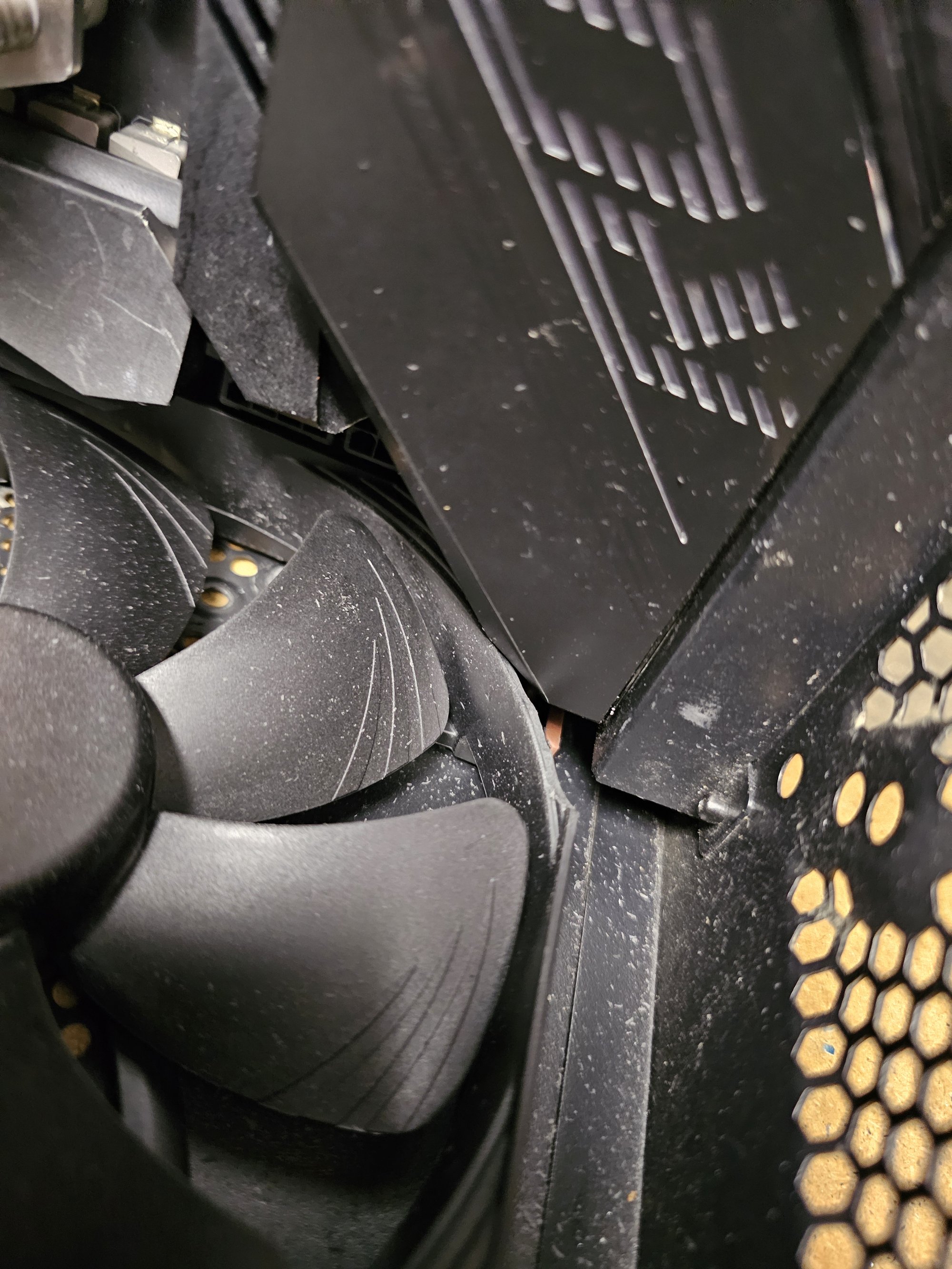
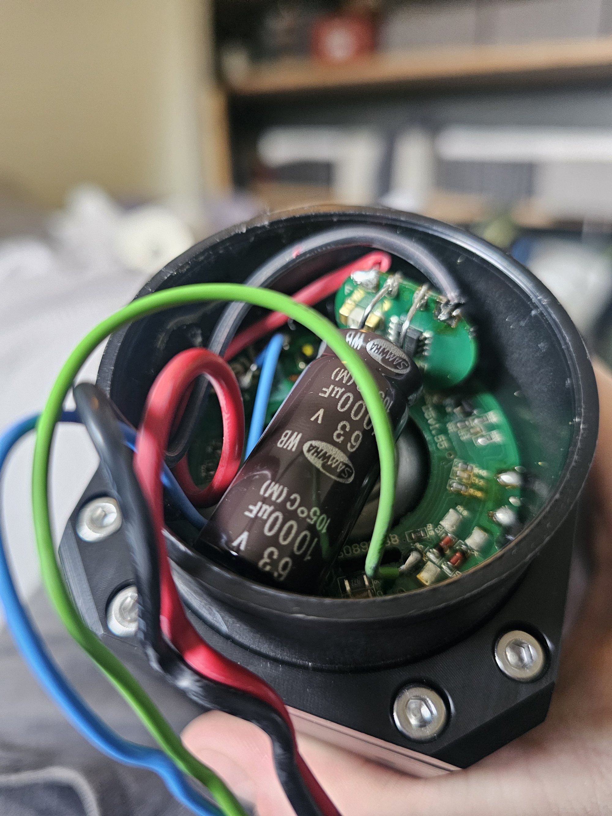
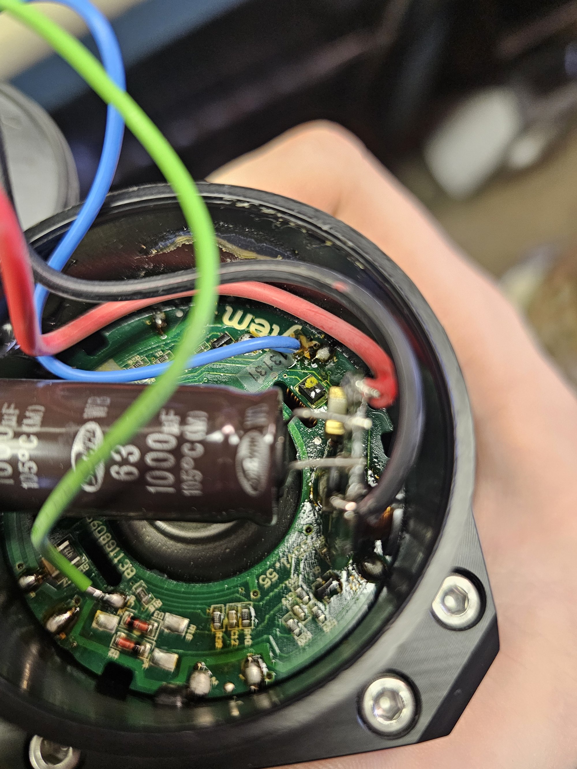
Watercooling Overhaul Gallery
Revision Archive
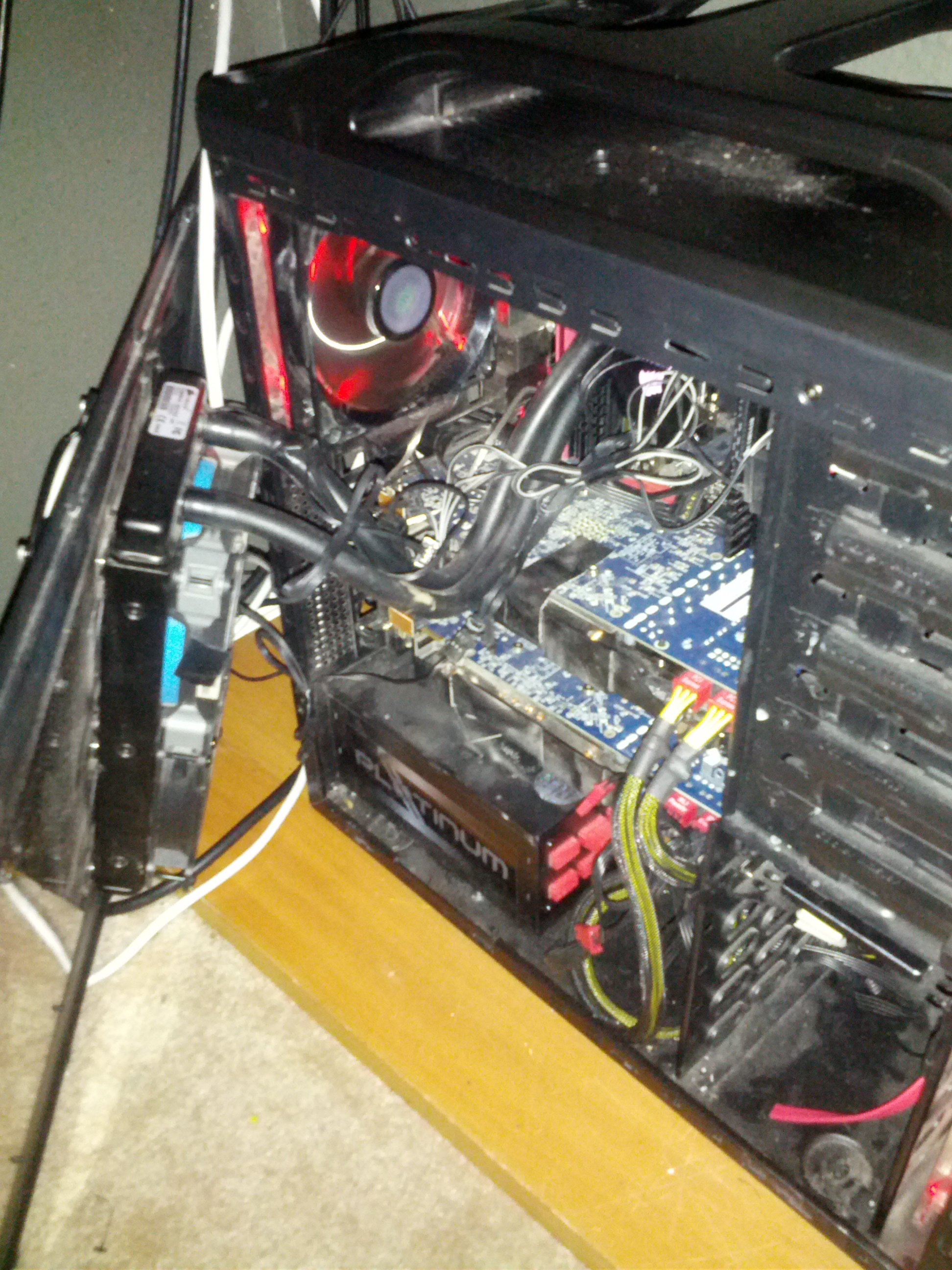
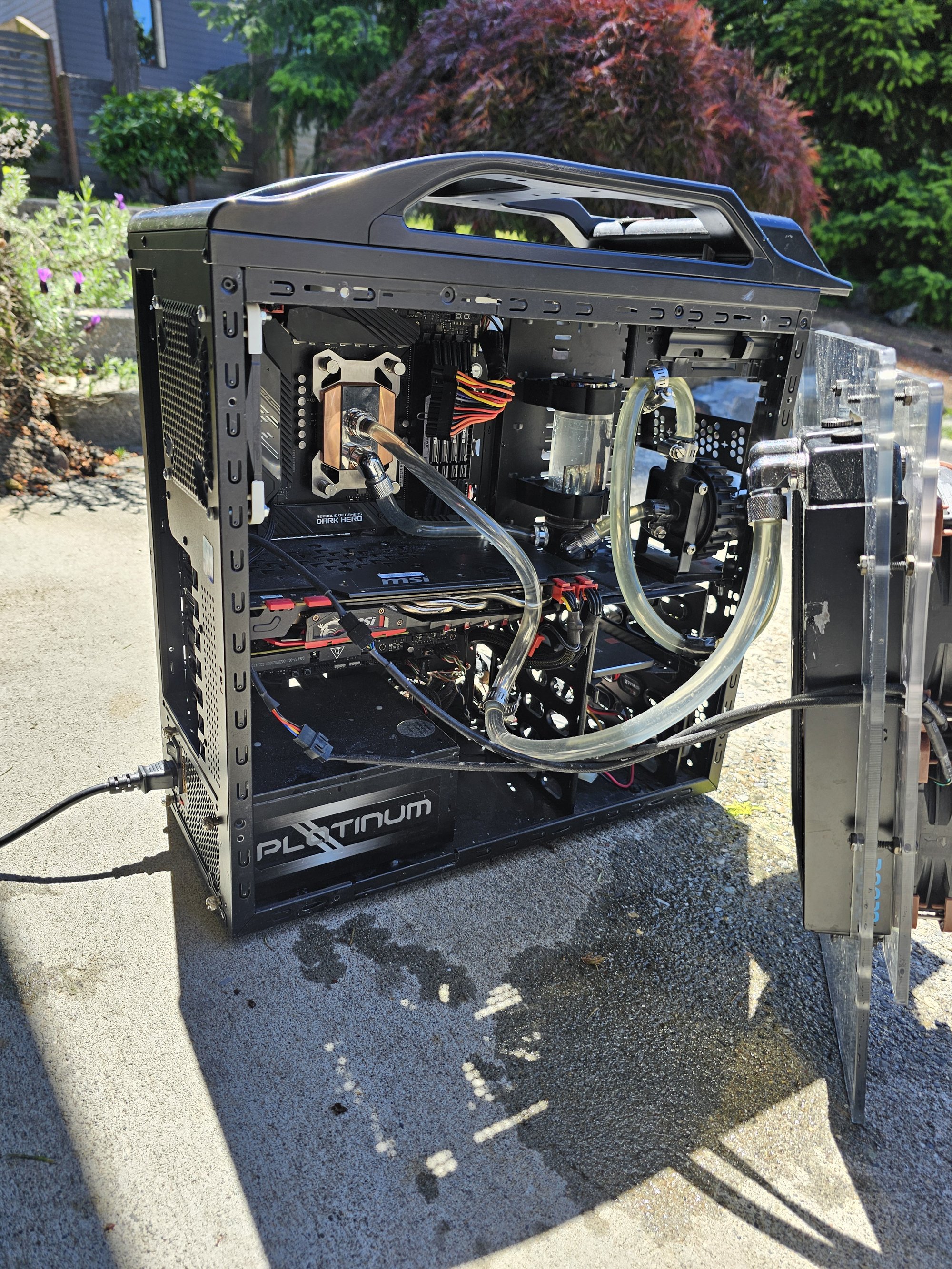
Here's what its looked like over the years. The middle picture is when I swapped in a 5900x but the rest of the hardware supported a 5820k for ~6 years. Take the single rad ryzen pic and swap in an x99 deluxe, 4x8gb 2666 vengeance, and a phobya uc-1 extreme block.
The old picture was an fx8150 /w 32GB 1866CL10 and 2x7950 @ 1200 core.