Battery Backup (UPS)
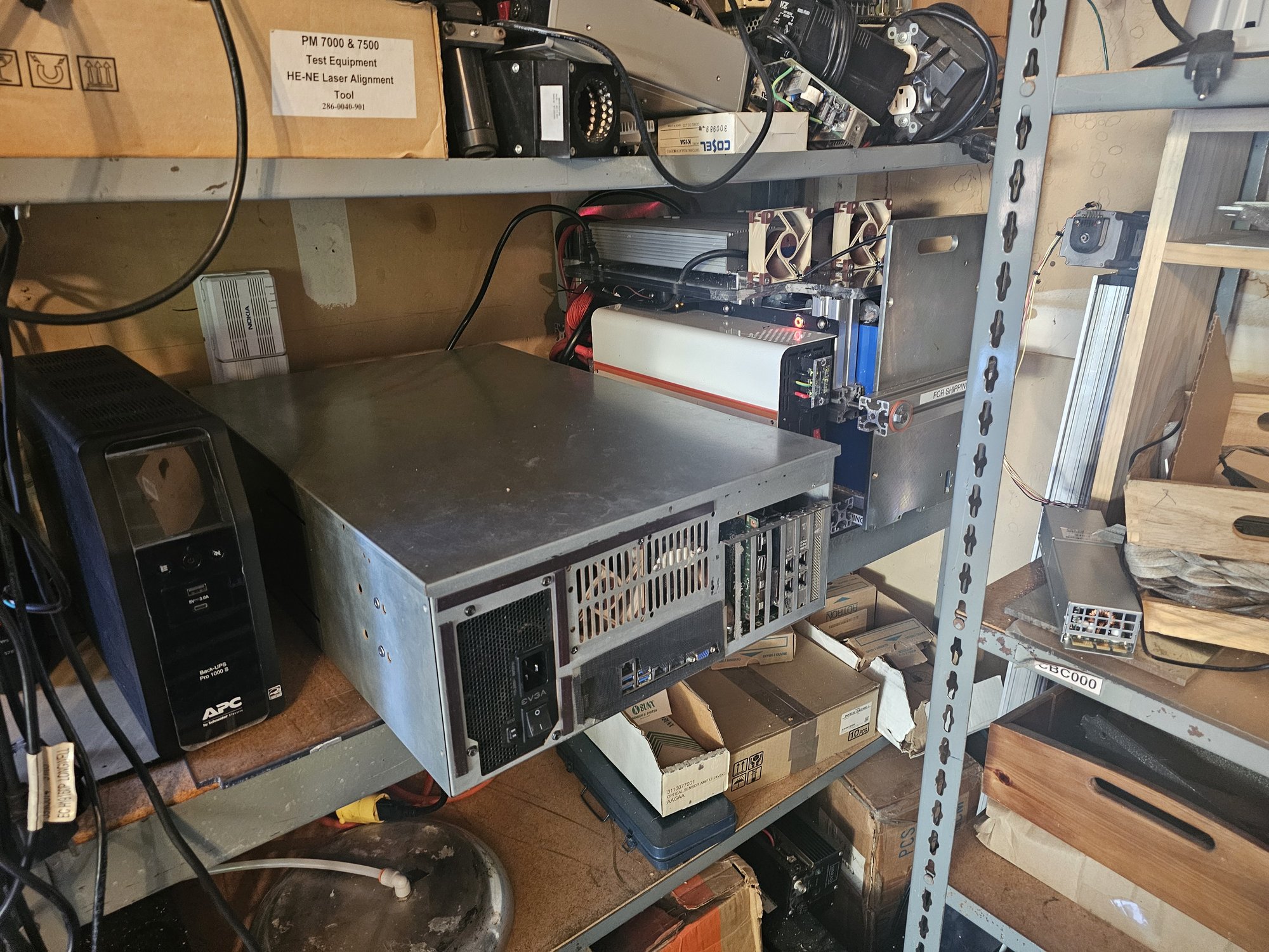
Back when I built Dreadnought I still believed lead-acid was the only solution without spending many thousands on a super premium system. The APC brand lead acid rackmount refurb piece of shit I did buy worked about 2 years before exhibiting signs that it wasn't really functioning anymore, and then it betrayed me.
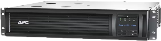
Do not buy these
A big problem I have is that Dreadnought has recorded peaking at over 1250w. Pretty much every consumer UPS caps out at about 1kw. The only cost-effective option I know of is grabbing a Jackery Explorer 1000v2 on sale, which I did already have, but I wasn't in a hurry to start trying to modify a Jackery for 24/7 service.
Another sticking point with me is something I learned from running Supermicro servers, which is how finnicky high efficiency supplies can be with Automatic Transfer Switch delay times.
My dream was a high efficiency online (double conversion) UPS, so I would have total grid isolation, and not have to worry about switchover times at all, which would mean I could use it on finnicky tech. Dreadnought uses a consumer EVGA 1600 P+ power supply though so I dont believe its a critical factor.
Initial load testing
Components
Battery management was new to me. I had a surprisingly difficult time figuring out a recipe for what I wanted as practically all online diy content is centered solely around off-grid power solutions i.e. solar, boat / RV, whole home, etc. The only thing I knew going in is I needed a genuine sine wave inverter.
BMS
I quickly learned about Battery Management Systems (BMS), and settled on the JK-BMS brand. A BMS physically serves as a low side switch, and an inter-cell charge balancer. It'll typically come with one or more thermal probes as well, and has a myriad of health monitoring tactics.
Cells
Capacity targeting imo is essentially dependent on you deciding what DC voltage you're going to target. Accepted DC voltages are 12,24,36,48v, all nice and normal. These are obviously achieved by different lengths of series configuration (4,8,12,16) of cells. Sets can obviously be paralleled for increased current. You should always target the highest possible DC line voltage. This will minimize losses, and greatly simplify the design and reduce costs, since you have to deal with less amperage (Pd=I^2 * R). Your DC line voltage locks you into the power supply AND the inverter you're using. BMSes typically have a working range.
I noticed the vast majority of cost was going to be associated with the power throughput requirements of the inverter and power supply, and baseline unit price of any given cell. I therefore opted for the largest high prismatic cells I could find, and chose CATL314's. I see some people online complaining about these being automotive rebrands and issues with the post welding, but I didn't experience any issues, and I have no idea why it being an automotive surplus is an issue. Eve cells are obviously fantastic, but imo they are a true premium.
Chassis
LifePO4 cells have a magic property in that they are not self-combustible. The temperature they burn at in the event of catastrophic failure is lower than their ignition point, so they'll just sit around and slowly smoulder.
That being said I still wanted to build something I could be proudly confident in, and I wanted to maintain a healthy environment for my cells because these things aren't cheap and I don't want them to degrade on me.
I had no idea you're supposed to compress them. I have a ton of 1sqin 80/20 extrusion and went in thinking I'd use that (a lot..). I found some youtubers and other people and it seems the common meta-strat is ratchet-straps to achieve compression, and to just stop there. These cells are so resiliant you can beat on them constantly without major issues.
Power supplies
I had no idea what these cells needed in way of charging. I tried several "chargers" as I will call them now, but I needed one that specifically had "float charge" capabilities. The vast majority of chargers are designed to charge a cell bank to full, then shut off. What happened to me was my bank charged, the charger shut off, and my bank began discharging, resulting in loss of power several days later.
It took a lot of searching but I found the HEP-1000-24 (24 = 24vdc) from Mean-Well to be a perfect candidate. I also found these units appear to sell often enough on ebay for far below what Mouser or Digikey would charge you. They are passively cooled (so I can control how noisily to cool them), and come with a ton of bells and whistles. I argued that 1000w of continuous supply capability, so maybe 900w out-the-door to my server, was adequete enough as 8kwh would easily bridge any gap there for up to a week. I then found a used HEP-1000-24 selling FAR below MSRP so I bought that and am running two in parallel.
Parallel Supplies
There is a really cool cheat here. You can run power supplies / chargers in parallel without active current balancing, if they are CV/CC (constant voltage + constant current) AND you are loading them with batteries. The batteries act as a sort of giant charge well that will provide an essentially infinite load to the chargers, so there are no feedback issues where the supplies are constantly trading off load.
I cannot recall ATOW what I'm float charging these cells to. But I remember it is pretty gentle. I'm going for longevity, and don't mind blowing a couple hundred watt hours to achieve that. I also have a charge curve set up on the HEP-1000-24 supplies.
Programming Mean-Well HEP
IMPORTANT:: You NEED the dumbass SBP-001 programmer from Mean-Well in order to program these supplies, and they NEED to be programmed to be used in this scenario.
The supplies you get are almost guaranteed to be PMBUS variants. CANBUS is going to be rare and reserved for crazy enterprise integration stuff.
The Build
I was initially looking around for a snug fitting container to house the cells in. I ended up loving this chassis because it has great protection while being totally breathable.
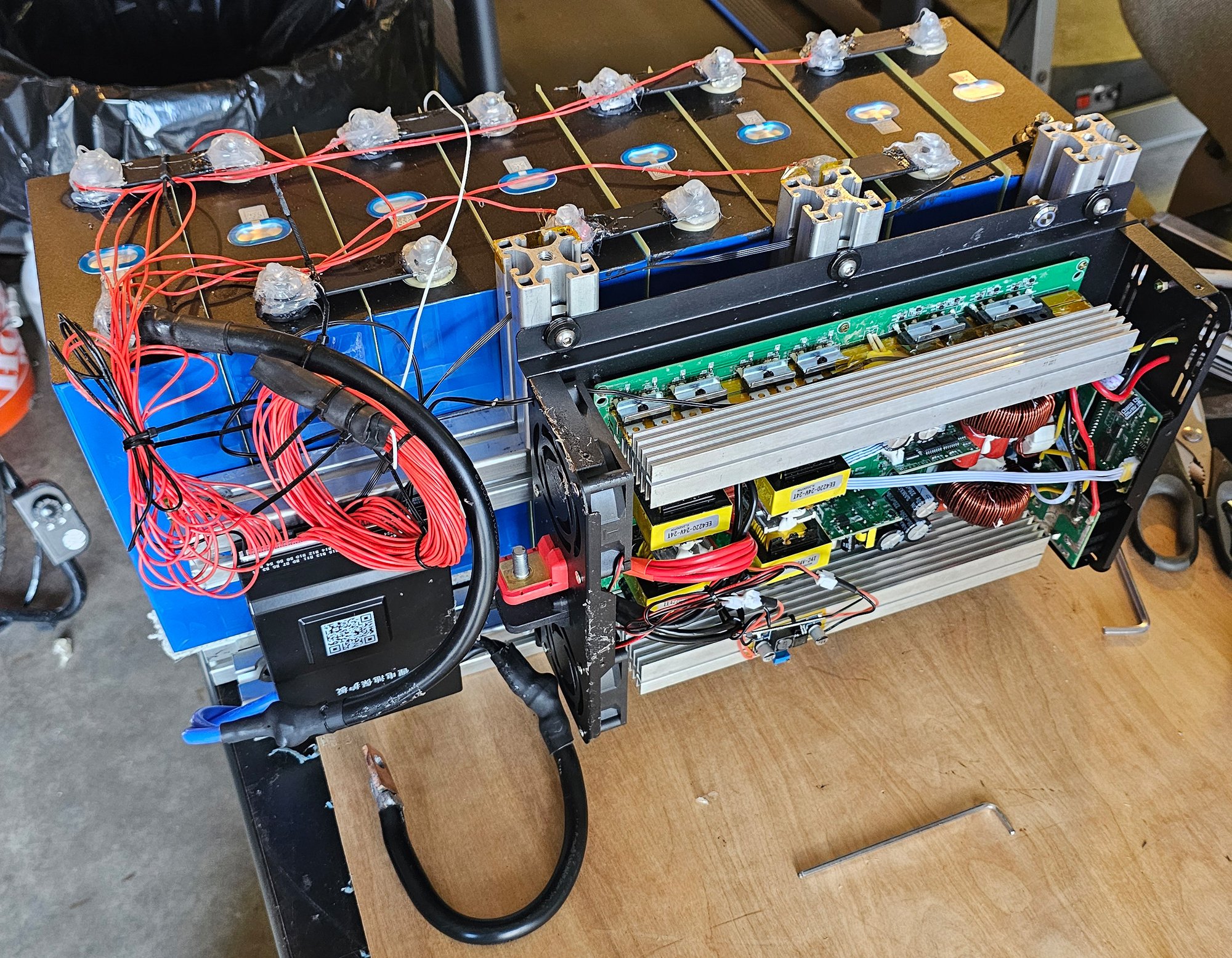
The entire chassis is disassemblable with two M8 allen keys I keep on it at all times. My "trick" to making the design work was drilling holes through the centers of the extrusion where I needed fastener access to lower levels. I used official 80/20 rail nuts to lash everything together. The bottom of the chassis is solid extrusion. The padding is free carpet samples, which are non-conductive nylon/PP/PE/etc. The inner walls of the extrusion around the cells are thickly coated in kapton tape (polyimide tape).
The compression plates for the cells are 1/4in stainless steel, likely 17-4. To achieve a proper compressive force I fashioned silicone compression washers, which is the orange in the pictures. I torqued the cells to "nice and snug" ftlbs, where I took a rough measurement of the before and after lengths to measure the compression (as you're supposed to do), but I cannot remember the specifications atow.
The cell terminal posts are all capped with silicone. The JKBMS is mounted with silicone gel tape. JKBMS-monitored temperature probes are in the rear cell area, and in the inverter front area embedded in the heatsink near some of the IGBT's.

Power Conductor Termination
I do not fuck around with connection quality. I have two books concerning the art of crimping. I did not want to play around with random amazon wire and crimp eyelet being a match made in heaven. I also did not want to have to go buy low gauge shitty crimpers, since I cannot seem to find mine.
I opted to solder the eyelets with non-dendritic solder. If done properly, this is a superior connection method assuming you KNOW the device is not going to get 350F+ hot. 99.999% of the time it also seems that people who solder high amperage connections like these don't know what they're doing. You can tell they end up with hollow connections i.e. not completely filled with solder. Doing this properly means the cross sectional contact area is a solid brick the whole way through, and also you don't have solder wicked 3 inches up under the wire jacket (which is trickier to avoid with higher strand wire, which I use).
Here's the trick: pre-flux the wire, then clamp the eyelet with the wire cup facing upwards and heat with a blowtorch and fill with solder to form a crucible. get it quite hot but not stupid, then steadily submerge the wire and hold until air cooled. You want enough heat in the solder to heat the wire to the point where the solder can bond to it, and not so much that it stays molten and stars eating the jacket. Warning: I used normal electronics flux (alpha 856) which catches fire at the temperatures I went to. Its fine but its just something to be aware of. Bonus points for a damp rag or something to hold the jacketing to quell any fires and keep the jacket from getting charred.
DIY Terminals
The Shenzen Special inverter I got off amazon had undersized posts. In order to achieve good surface area contact I had to make my own terminals. I kludged this with some copper bar I had laying around. I soldered 2 gauge cable to it with a technique I figured out after a couple attempts:
- copper bar should be sanded fresh
- use random bare wire (I used 20awg solid core) and lash target cable onto bar with many revolutions of bare wire.
- pre-flux connection
- heat solder in crucible and pour onto connection
- let cool
- clamp by the jacketed cable in vise with connection facing upwards
- pre-flux connection
- wrap cable in damp cloth
- blowtorch up and away, the end of the bar, until connection solder gently melts
- apply more solder as needed
- gingerly move flame over connection temporarily as needed to seat solder
The goal here is to prevent the jacket from getting too hot, and to prevent solder from wicking up into the wire. The crucible pour step is good because it very quicky gets a lot of solder very close to where it needs to be, so when you do the real blowtorch heat, its like having many people concurrently feeding solder into all areas simultaneously, i.e. its faster than you could ever feed it in yourself because its already present on the whole surface at once.
Inverter Fan Mods
The inverter I got is a real piece of shit. I still need to get around to swapping out the AC outlets on it because the current ones are so sloppy it actually makes me nervous.
The fans it came with were 70mm DC trash, and the thermal probe driven fan curve constantly flipped between low and max every second. I swapped in 80mm Noctua fans (NF-A8). I took the fans to a belt grinder and ground down the housing corners to conform to the contours of the inverter, and they fit like gloves. To power them I hooked up a static PWM fan driver to the 12v auxiliary power off one of the power supplies and set it appropriately.
